Radiation image generating system

Inactive Publication Date: 2006-09-28
KONICA MINOLTA MEDICAL & GRAPHICS INC
View PDF3 Cites 24 Cited by
  • Summary
  • Abstract
  • Description
  • Claims
  • Application Information

AI Technical Summary

Benefits of technology

[0008] An object of the present invention is to make it possible to check a communication state of a radiation image detector at various locations and to prevent an unnecessary re-performance of an image generation.
[0015] Normally, when a radiation image detector is used, the detector is operated by a console installed in each of an image generation room, a hospital ward, an operating room and the like. In other words, although upon the use it is necessary to install the radiation image detector within a range within which the console is capable of communicating, when there is an abnormality in a communication state under such a condition, an image information obtained by the image generation is not transmitted to the console. Therefore, as the present invention, after the console control unit transmits a replying instruction signal for instructing a reply to the detector communication unit, the console control unit detects whether there is a replying signal based on the instruction. Then, when the replying signal is not inputted to the console communication unit, the console control unit controls the reporting unit to report that a communication abnormality occurs. Thereby, it is possible to recognize an abnormality of the communication state before an unnecessary image generation is performed. Consequently it is possible to reduce exposure dose to a patient by unnecessary re-performance of the image generation.

Problems solved by technology

However, by the conventional diagnosis function, it is not possible to check a communication state of the cassette-type FPD.
In other words, even when the image generation unit normally functions, if a communication state of the cassette-type FPD is not normal, it is not possible to transmit a correct image.

Method used


Image

  • Radiation image generating system
  • Radiation image generating system
  • Radiation image generating system

Examples


Embodiment Construction

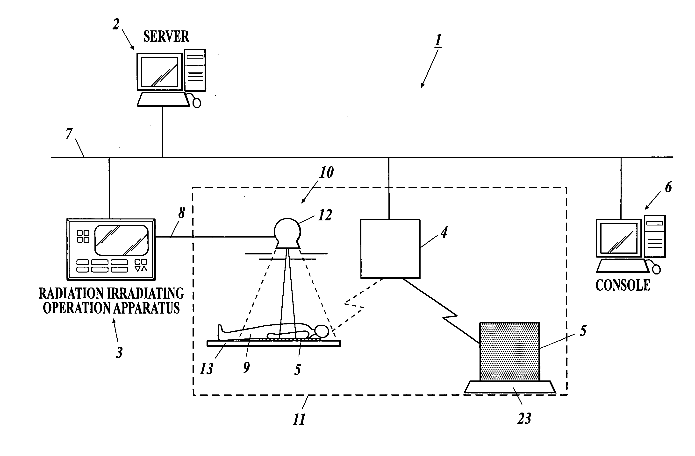
[0028] Hereinafter, an embodiment of the present invention will be described with reference to FIG. 1 to FIG. 6. FIG. 1 is a view showing a schematic structure of one embodiment of a radiation image generating system to which a radiation image detector relating to the present invention is applied.

[0029] A radiation image generating system 1 of the present embodiment is, for example, a system which is applied to a radiation image generation performed in a hospital. As shown in FIG. 1, the radiation image generating system 1 comprises a server 2 for managing various information regarding an image generation, a patient and the like, a radiation irradiating operation apparatus 3 for performing an operation regarding a radiation image generation, a base station 4 for a communication according to a wireless communication system such as a wireless LAN (Local Area Network) or the like, and a console 6 for controlling a radiation image detector 5 and for performing an image processing or th...


PUM


Abstract

A radiation image generating system having: a radiation image detector to obtain an image information; and a console to control the radiation image detector, wherein the radiation image detector comprises a detector communication unit communicating to the console, and a detector control unit to which a signal from the detector communication unit is inputted, the console comprises a console communication unit communicating to the detector communication unit, a console control unit controlling the console communication unit, and a reporting unit controlled by the console control unit, and after the console control unit controls the console communication unit to transmit a replying instruction signal for instructing a reply to the detector communication unit, the console control unit detects whether there is a replying signal based on the instructing, and when the replying signal is not inputted, the console control unit controls the reporting unit to report that a communication abnormality occurs.

Description

BACKGROUND OF THE INVENTION [0001] 1. Field of the Invention [0002] The present invention relates to a radiation image generating system. In particular, the present invention relates to a radiation image generating system for generating a radiation image as represented by an X-ray image. [0003] 2. Description of Related Art [0004] So far, in a medical diagnosis, a radiation image which is obtained by irradiating a radiation such as an X-ray or the like to a subject and by detecting an intensity distribution of the radiation transmitted through the subject has been widely in use. These days, a radiation image generating apparatus using an FPD (Flat Panel Detector; radiation image detector) that detects a radiation and converts the detected radiation into an electric energy to be detected as a radiation image information is being proposed upon radiography. In such a radiation image generating apparatus, a diagnosis function to check a state of an image generating unit is provided for ...

Claims


Application Information

Patent Timeline
IPC IPC(8): G06K9/00
CPCA61B6/00A61B6/032A61B6/4283A61B6/4411A61B6/566G03B42/02A61B6/4494
Inventor OHARA, HIROMU
Owner KONICA MINOLTA MEDICAL & GRAPHICS INC
Why Eureka
Try Eureka