Radio frequency power amplifier and method using an amplitude control system

a radio frequency power amplifier and control system technology, applied in power amplifiers, negative-feedback circuit arrangements, transmission, etc., can solve the problems of difficult or impossible to accurately receive/demodulate signals, battery size and hence weight and cost increase directly with power requirements, and non-ideal characteristics of components of radio frequency power amplifiers

Inactive Publication Date: 2006-09-28
PWRF
View PDF31 Cites 9 Cited by
  • Summary
  • Abstract
  • Description
  • Claims
  • Application Information

AI Technical Summary

Problems solved by technology

Small distortions in the form of the output signal relative to the input can cause the radio frequency power amplifier output signal to interfere with other radio services, in violation of regulatory requirements, or make it difficult or impossible to receive/demodulate the signal accurately.
These distortions may be caused, for example, by the fact that the characteristics of the components of which a radio frequency power amplifier is composed (e.g. transistors) are non-ideal, e.g., vary with the electrical currents that they carry, which necessarily include the signal being reproduced.
The power (90 Watts in the example) “wasted” in this way causes many problems.
When equipment is battery-operated (e.g. in cell phones or in fixed installations (base transmitters) that are running on backup batteries during a power failure), ...

Method used


Image

  • Radio frequency power amplifier and method using an amplitude control system
  • Radio frequency power amplifier and method using an amplitude control system
  • Radio frequency power amplifier and method using an amplitude control system

Examples


Embodiment Construction

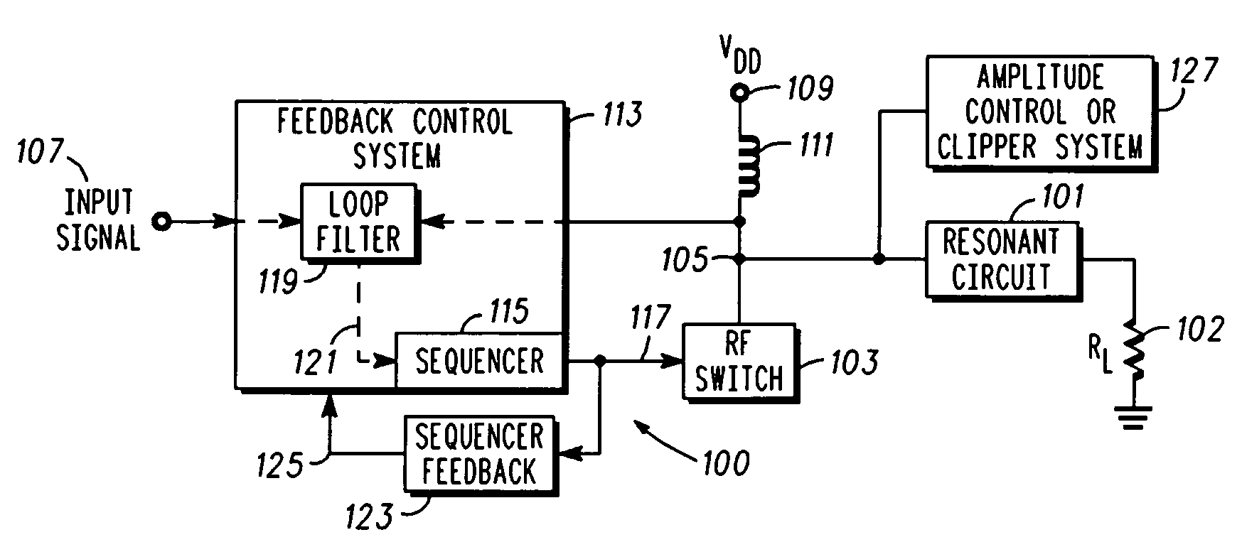
[0023] In overview, the present disclosure primarily concerns communication equipment including radio frequency transmitters or amplifiers such as used in infrastructure equipment including base stations or in communications units. Such radio frequency amplifiers for example, may be found in cellular, two-way, and the like radio networks or systems in the form of fixed or stationary and mobile equipment. The fixed equipment is often referred to as base stations or transmitters and the mobile equipment can be referred to as communication units, devices, handsets, or mobile stations. Such systems and equipment are normally used to support and provide services such as voice and data communication services to or for such communication units or users thereof.

[0024] More particularly, various inventive concepts and principles are embodied in systems or constituent elements, communication units, transmitters and methods therein for providing or facilitating radio frequency amplifiers or p...


PUM


Abstract

A radio frequency power amplifier and corresponding method is arranged and configured to drive a resonant load. The radio frequency power amplifier includes a radio frequency switching stage with an output that is coupled to a resonant circuit. The switching stage is configured to provide an output signal with amplitude modulation corresponding to amplitude modulation of an input signal when powered from a fixed voltage power supply. The amplifier further includes a feedback control system coupled to the input signal and the output signal, where the feedback control system includes a sequencer configured to provide a sequencer output that is used to drive the radio frequency switching stage. The amplifier also includes an amplitude control system coupled to the output of the radio frequency switching stage and configured to limit an amplitude of the output signal and in some embodiments a power recovery system.

Description

RELATED APPLICATIONS [0001] This application is a continuation in part of pending application titled RADIO FREQUENCY POWER AMPLIFIER AND CORRESPONDING METHOD, Ser. No. 11 / 089,834 by Snelgrove et al., filed on Mar. 25, 2005, which is hereby incorporated herein in its entirety by reference. This application is related to co-pending application titled RADIO FREQUENCY POWER AMPLIFIER AND METHOD USING A PLURALITY OF FEEDBACK SYSTEMS, Docket number 34-003P01 filed Apr. 28, 2006, which is hereby incorporated herein in its entirety by reference. This application also claims priority from Provisional Application, Ser. No. 60 / 675,614, filed on Apr. 28, 2005 and Provisional Application, Ser. No. 60 / 675,704, filed on Apr. 28, 2005, which are also hereby incorporated herein in their entirety by reference.FIELD OF THE INVENTION [0002] This invention relates in general to communication equipment, and more specifically to radio frequency power amplifiers. BACKGROUND OF THE INVENTION [0003] Radio-fr...

Claims


Application Information

Patent Timeline
IPC IPC(8): H01Q11/12H04B1/04
CPCH03F1/02H03F1/0205H03F1/0238H03F1/34H03F3/24H03F2200/331H03F2200/78H03G11/02
Inventor SNELGROVE, WILLIAM MARTINLOVELACE, DAVIDWILSON, RICHARDMEKECHUK, KELLYBLEASE, THOMAS A. JR.
Owner PWRF
Why Eureka
Try Eureka