Method of performing a procedure within a disc

a technology of intervertebral discs and procedures, which is applied in the direction of osteosynthesis devices, prostheses, catheters, etc., can solve the problems of patient slipping, high invasiveness of abdominal organs, and devices that cannot be used to manipulate anular and nuclear tissue in a precise and minimally invasive manner, so as to facilitate patient guidance, facilitate the effect of reliable and accurate guidan

Inactive Publication Date: 2006-09-28
INTRINSIC THERAPEUTICS
View PDF15 Cites 90 Cited by
  • Summary
  • Abstract
  • Description
  • Claims
  • Application Information

AI Technical Summary

Benefits of technology

[0015] Various embodiments of the current invention are particularly advantageous because they provide active controlled direction of the working end of the instrument within the anulus or nucleus. Further, several embodiments provide access to the posterior portion of the anulus using a posterior surgical approach. In various embodiments, access to the posterior anulus, via circumferential navigation of the instrument as it is deflected from the lateral, anterior, opposite lateral, and finally to the posterior anulus, is avoided. This is advantageous because circumferential deflection of the working end of the instrument within the anulus can result in the tip of the instrument passing through a fissure in the posterior anular surface and outward to the spinal cord. This can occur because the circumferential navigation from a typical posterior surgical approach eventually directs the tip perpendicular to the posterior anular surface, which may contain lesions large enough to allow protrusion of the tip directly through to the spinal cord.
[0016] There is provided in accordance with one aspect of the present invention, a device for treating the spine. The device comprises an elongate guide having a longitudinal axis. An axially moveable actuator is carried by the guide. A probe is movable with the actuator, and a deflection surface is carried by the guide. Axial movement of the actuator causes the probe to advance along the deflection surface and extend away from the guide at an angle to the longitudinal access of the guide.
[0023] One or more embodiments disclosed herein provide a convenient, reliable, and accurate way to measure the anular thickness and the internal dimensions of the disc space normally occupied by the nucleus pulposus.
[0024] Several embodiments of this invention provide a device useful in determining various disc dimensions in order to enable a surgeon to size various implants and tools and facilitate their guidance within the disc.

Problems solved by technology

The most common symptoms of herniation include pain radiating along a compressed nerve and lower back pain, both of which can be crippling for the patient.
Accordingly, these devices cannot be used to manipulate anular and nuclear tissue in a precise and minimally invasive manner.
Although an anterior surgical approach provides direct access to intervertebral discs, it is highly invasive to the abdominal organs.
Thus, surgery is typically more complicated and time consuming.
An posterior-lateral aspect approach is the least invasive of these methods but provides limited and oblique access to the disc and its interior.
These devices tend to be limited by the size of the cannula which houses the instrumentation and its ability to maneuver around vertebral bodies and delicate tissues of the spine.
However, if used in an antero-lateral spinal approach, these tools are generally limited by the indirect approach necessitated by the laminae and spinous processes of the adjacent vertebrae, and thus, access to tissues is substantially hampered.

Method used


Image

  • Method of performing a procedure within a disc
  • Method of performing a procedure within a disc
  • Method of performing a procedure within a disc

Examples


Embodiment Construction

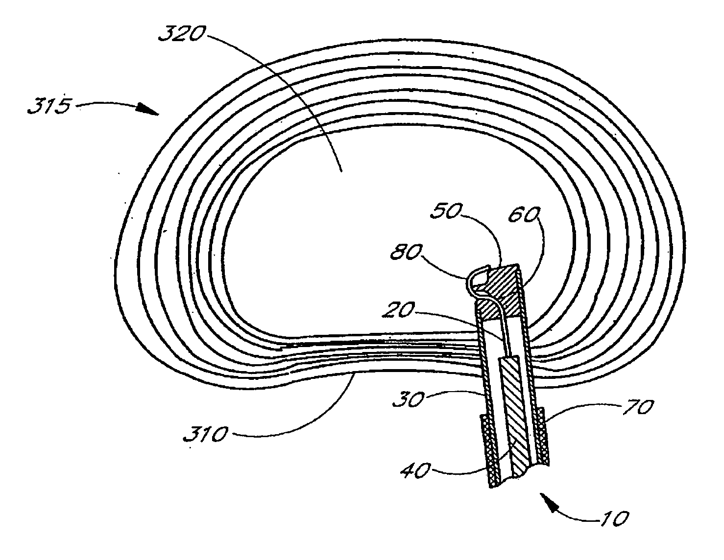
[0054] In one aspect of the invention, there is provided a guide such as a hollow delivery cannula having a distal end and a proximal end. The guide is dimensioned to fit within a small anulotomy as might be created by a surgeon or through a naturally occurring hole or lesion in the anulus. An advancer, push rod, or actuator is axially moveably carried by the guide, and coupled to a flexible probe member. The flexible probe member has a proximal end connected to the advancer and distal end connected to or formed into a probe tip.

[0055] The probe is advanceable outwardly from the distal end of the cannula via axial movement of the advancer within the cannula. In the illustrated embodiment, the probe member exits through a slot having a curved pathway or deflection surface located at the distal end of the cannula and can be advanced outwardly therefrom generally at an angle of between about 30 to about 150 degrees relative to the cannula's longitudinal axis. Accordingly, when the dis...


PUM

PropertyMeasurementUnit
angleaaaaaaaaaa
lengthaaaaaaaaaa
lengthaaaaaaaaaa

Abstract

The present invention relates generally to intervertebral disc devices and methods and instrumentation for intervertebral disc procedures. Methods include performing procedures such as implant delivery, tissue manipulation, tissue diagnostics, and therapeutic and diagnostic agent delivery at selected locations within intervertebral discs.

Description

RELATED APPLICATIONS [0001] This application is a continuation of co-pending U.S. application Ser. No. 10 / 359,516, filed Feb. 5, 2003, which is a continuation-in-part of U.S. application Ser. No. 10 / 020,507, filed Dec. 11, 2001, which claims benefit to U.S. Provisional Application No. 60 / 298,605, filed Jun. 14, 2001, and wherein Ser. No. 10 / 359,516 is a continuation-in-part of co-pending U.S. application Ser. No. 10 / 055,504, filed Oct. 25, 2001, which claims benefit to U.S. Provisional Application No. 60 / 311,586, filed Aug. 10, 2001, and wherein Ser. No. 10 / 359,516 is a continuation-in-part of co-pending U.S. application Ser. No. 10 / 325,320, filed Dec. 19, 2002, which is a continuation of U.S. application Ser. No. 09 / 696,636, filed Oct. 25, 2000, now issued as U.S. Pat. No. 6,508,839, which is a continuation-in-part of U.S. application Ser. No. 09 / 642,450, filed Aug. 18, 2000, now issued as U.S. Pat. No. 6,482,235, which is a continuation-in-part of U.S. application Ser. No. 09 / 608,...

Claims


Application Information

Patent Timeline
Patent Type & Authority Applications(United States)
IPC IPC(8): A61F2/44A61F2/46A61B17/88A61B5/107A61B17/00A61B17/22A61B17/32A61B17/34A61B17/70A61B19/00A61F2/00A61F2/02A61F2/28A61F2/30
CPCA61B5/1076A61B5/4514A61B17/320708A61B17/70A61B2017/00261A61B2017/22077A61B2017/320044A61B2017/3445A61B2019/461A61B2019/462A61F2/2846A61F2/30723A61F2/30907A61F2/441A61F2/442A61F2/4601A61F2/4611A61F2/4657A61F2002/2817A61F2002/30062A61F2002/30075A61F2002/30131A61F2002/30224A61F2002/30228A61F2002/30291A61F2002/30462A61F2002/30571A61F2002/30583A61F2002/30589A61F2002/30677A61F2002/30777A61F2002/30785A61F2002/4435A61F2002/444A61F2002/448A61F2002/4627A61F2002/4635A61F2002/4658A61F2002/4661A61F2002/4662A61F2210/0004A61F2210/0061A61F2210/0085A61F2220/0075A61F2230/0013A61F2230/0069A61F2230/0091A61F2310/00017A61F2310/00023A61F2310/00029A61F2310/00293A61F2310/00365A61F2310/0097A61F2310/00976A61B2090/061A61B2090/062
Inventor LAMBRECHT, GREGORY H.MOORE, ROBERT KEVINEINHORN, JACOB
Owner INTRINSIC THERAPEUTICS
Why Eureka
Try Eureka