Cooling and heating system

a technology of cooling and heating system, applied in the direction of refrigeration components, light and heating apparatus, refrigeration machines, etc., can solve the problems of difficult control of heat exchanger and compressor capacity, inability to obtain condensation temperature uniquely, and inability to achieve high condensation pressure. achieve the effect of maximizing the coefficient of performan

Inactive Publication Date: 2006-10-05
SANYO ELECTRIC CO LTD
View PDF4 Cites 53 Cited by
  • Summary
  • Abstract
  • Description
  • Claims
  • Application Information

AI Technical Summary

Benefits of technology

[0009] According to the present invention, in the cooling and heating system in which the refrigerant is used in the supercritical state, cooling and heating capacity can be controlled so as to maximize a coefficient of performance.

Problems solved by technology

Therefore, there is a problem that the condensation pressure (high pressure) cannot be uniquely obtained from the condensation temperature (this refers to a high-pressure-side temperature because condensation does not occur in actual) unlike the fluorocarbon refrigerant, and both of the condensation temperature and the condensation pressure have to be measured on the high pressure side in order to grasp the state of the refrigerant.
Therefore, it has been difficult to control the capacities of the heat exchanger and the compressor so as to maximize the coefficient of performance.

Method used


Image

  • Cooling and heating system
  • Cooling and heating system
  • Cooling and heating system

Examples


embodiment 1

[0037] In the present embodiment, there will be described an operation control by a high pressure and an evaporation temperature with reference to FIGS. 4, 5, 6, and 7.

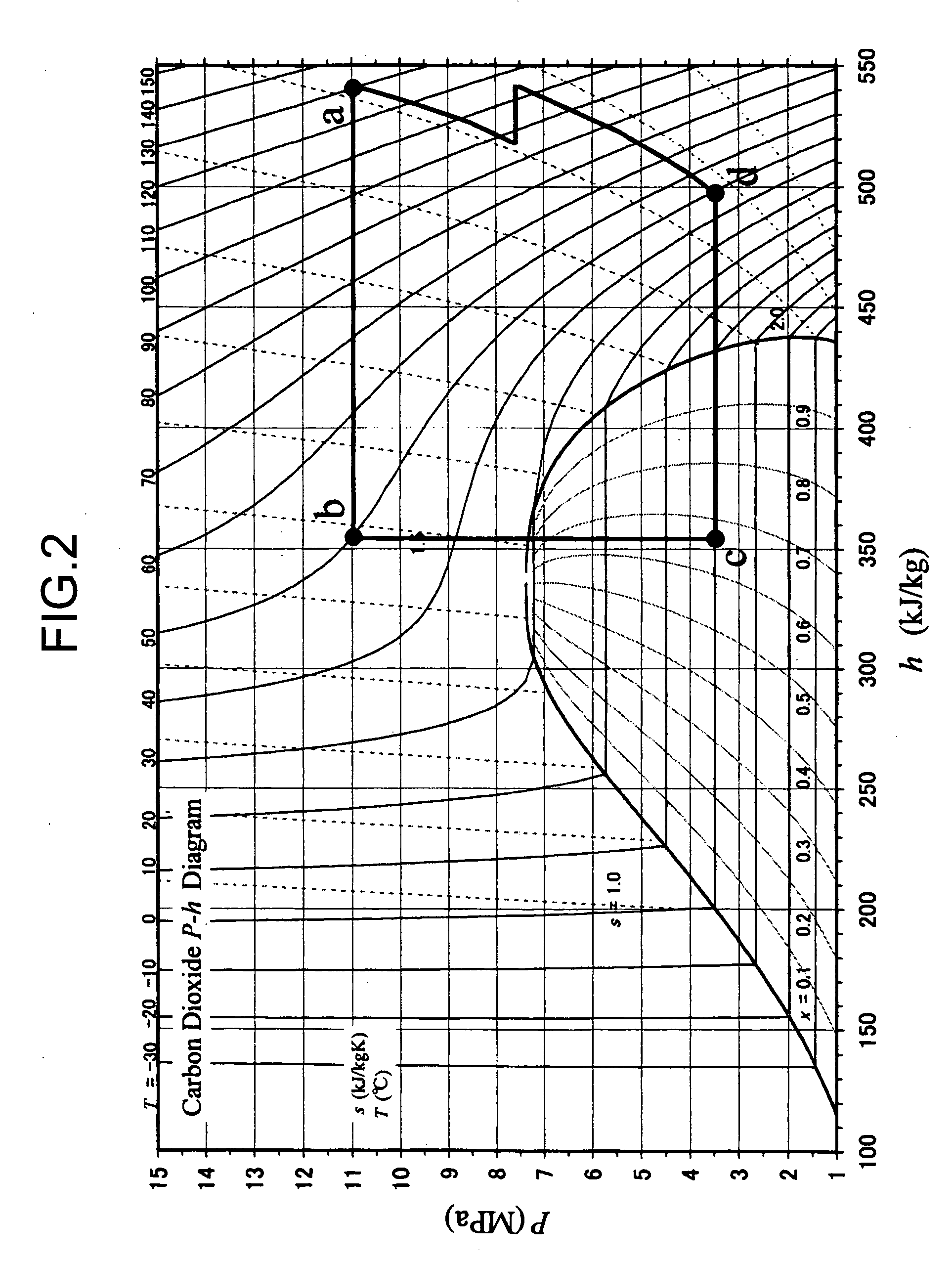
[0038] First in the present embodiment, as shown in a control flow (B1) of a thermal load balance control of FIG. 4, an evaporation temperature TEVA is measured (S150). A place to be measured differs with an operation state of a cooling and heating system 130. When the state c shown in FIG. 2 advances to the state d, a temperature during phase change of the refrigerant (carbon dioxide) from a liquid to a gas is the evaporation temperature TEVA. At this time, since the evaporation temperature TEVA and an evaporation pressure PEVA are uniquely determined, an object to be measured may be the evaporation pressure PEVA.

[0039] Next, an outlet refrigerant temperature TGC of the gas cooler is measured. Here, if the heating operation is performed in an out door unit 105a shown in FIG. 5 (S151), the outlet refrigerant tempera...

embodiment 2

[0042] In the present embodiment, there will be described an operation control by a discharge temperature and an evaporation temperature with reference to FIGS. 8, 9, 10, and 11.

[0043] First in the present embodiment, as shown in a control flow (C1) of a thermal load balance control of FIG. 8, an evaporation temperature TEVA is measured (S250). A place to be measured differs with an operation state of a cooling and heating system 230. When the state c shown in FIG. 2 advances to the state d, a temperature during phase change of the refrigerant (carbon dioxide) from a liquid to a gas is the evaporation temperature TEVA. At this time, since the evaporation temperature TEVA and an evaporation pressure PEVA are uniquely determined, an object to be measured may be the evaporation pressure PEVA.

[0044] Next, an outlet refrigerant temperature TGC of the gas cooler is measured (S252). Here, if the heating operation is performed in an indoor unit 205a shown in FIG. 9 (S251), the outlet refr...


PUM


Abstract

There is disclosed a cooling and heating system in which a refrigerant is used in a supercritical state and in which cooling and heating capacity can be controlled so as to maximize a coefficient of performance. A cooling and heating system 130 includes: an outdoor unit 101 indicating a compressor 102 and an outdoor heat exchanger 103a; a plurality of indoor units 105 including indoor heat exchangers 106; a high pressure tube 111; a low pressure tube 112; and an intermediate tube 113. The system includes: a refrigerant pressure detection unit PC01 for measuring a pressure of the refrigerant discharged from the compressor 102; a first refrigerant temperature detection unit TC03 which measures an outlet temperature of the refrigerant in a case where the outdoor heat exchanger 103 functions as a gas cooler and which measures an inlet temperature of the refrigerant in a case where the outdoor heat exchanger 103 functions as an evaporator; and a second refrigerant temperature detection unit TCO8 which measures an outlet temperature of the refrigerant in a case where the indoor heat exchanger 106 functions as a gas cooler and which measures an inlet temperature of the refrigerant in a case where the indoor heat exchanger 106 functions as an evaporator.

Description

BACKGROUND OF THE INVENTION [0001] The present invention relates to a cooling and heating system, more particularly to a cooling and heating system which uses a refrigerant in a supercritical state and which can control cooling and heating capacity so as to maximize a coefficient of performance. [0002] A cooling and heating system described in Japanese Patent Application Laid-Open No. 2004-226018 is known as a cooling and heating system in which a carbon dioxide refrigerant is used in a supercritical state. The system has an outdoor unit and a plurality of indoor units, the plurality of indoor units can be operated at the same time in a cooling operation or a heating operation, and the cooling operation and the heating operation can be performed in a mixed manner. Here, the cooling operation refers to an operation to be performed in a case where a set temperature of the indoor unit is lower than an indoor temperature, and the heating operation refers to an operation to be performed ...

Claims


Application Information

Patent Timeline
Patent Type & Authority Applications(United States)
IPC IPC(8): F25B13/00
CPCF25B9/008Y02B30/741F25B2309/061F25B2313/0231F25B2313/02791F25B2313/0314F25B2313/0315F25B2339/047F25B2500/19F25B2600/0253F25B2600/17F25B2700/1931F25B2700/21152F25B2700/2117F25B13/00Y02B30/70
Inventor OTAKE, MASAHISAKAMIMURA, ICHIROMUKAIYAMA, HIROSHISATO, KOJI
Owner SANYO ELECTRIC CO LTD
Why Eureka
Try Eureka