Method of operating a variable speed wind turbine

a wind turbine and variable speed technology, applied in the direction of motors, engine control, engine control parameters, etc., can solve the problems of high mechanical load, wind turbines may not necessarily be able to continuously adapt, and operation may not necessarily be optimal, so as to achieve maximum power coefficient, increase rotor speed, and increase electrical power

Active Publication Date: 2014-04-10
GE RENEWABLE TECH WIND BV
View PDF8 Cites 6 Cited by
  • Summary
  • Abstract
  • Description
  • Claims
  • Application Information

AI Technical Summary

Benefits of technology

[0017]Compared to prior art methods, wherein k is kept constant in order to maximize the power coefficient along the second operational range, in this aspect of the present invention, the operation of the wind turbine may be adapted for non steady-state conditions. For example, in case of significant wind shear (i.e. a significant variation of wind speed with height), it may be that more electrical power can be generated by modifying the rotor speed: a higher rotor speed may e.g. lead to a better aerodynamic performance for the rotor blades at heights greater than the nacelle (they may be closer to the ideal tip speed ratio along the top portion or sector of the rotor swept area). Even though the performance of the blades when they are below the nacelle may be worse, this can be compensated by the increased performance at greater heights. Also, the pitch angle, which is normally zero within this operational range, may be changed to achieve a similar effect: the default aerodynamic profile may be changed. This alternative profile may perform better along a certain sector / portion of the rotor swept area and even though it may perform worse along another sector, the overall performance may be improved.

Problems solved by technology

However, in non-steady state (transient) conditions, the operation may not necessarily be optimum.
A wind turbine may generally not be able to continuously adapt for these transient conditions, because of the large rotor inertia and because continuously adapting the operation would cause high mechanical loads, particularly in the drive train.

Method used


Image

  • Method of operating a variable speed wind turbine
  • Method of operating a variable speed wind turbine
  • Method of operating a variable speed wind turbine

Examples


Embodiment Construction

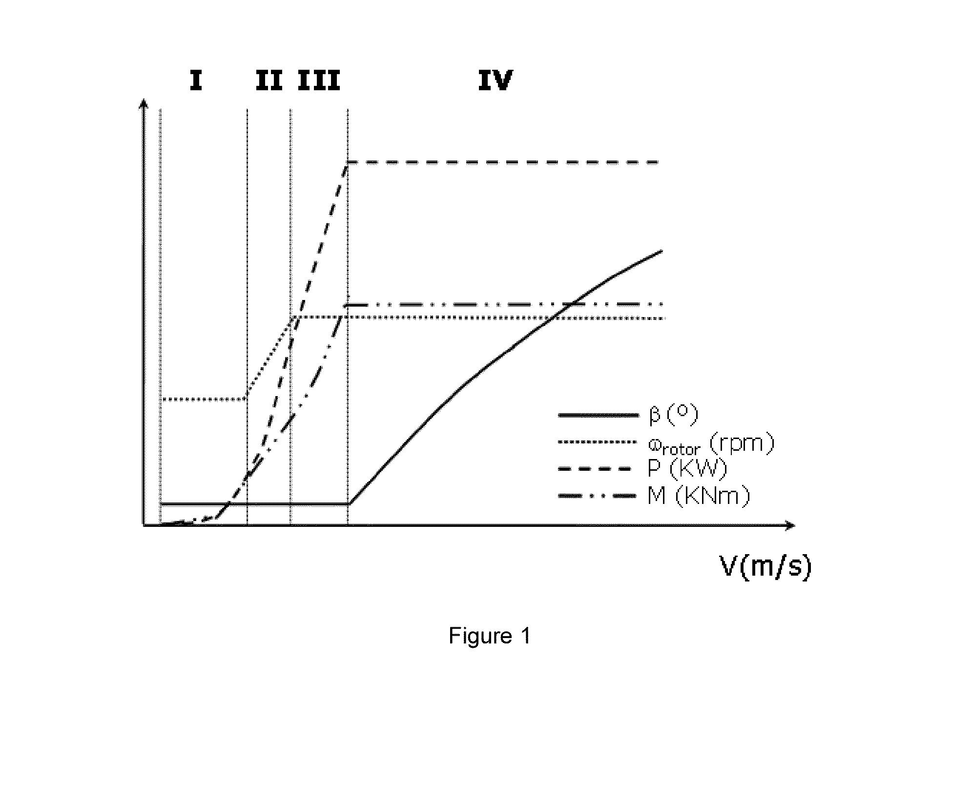
[0025]FIG. 1 illustrates a prior art control method and shows respectively the pitch angle (β), rotor speed (ωrotor), electrical power (P) and aerodynamic torque (M) at varying wind speeds.

[0026]As previously described, the pitch angle is generally not changed until nominal wind speed is reached, e.g. at 11 m / s. At a slightly lower wind speed, e.g. around 8.5 m / s, nominal rotor speed may be reached. At wind speeds above nominal wind speed, the pitch angle may be varied such as to maintain the aerodynamic torque substantially constant. The rotor speed, generator torque and electrical power generated may also be maintained substantially constant. This may be maintained from nominal wind speed to cut-out wind speed.

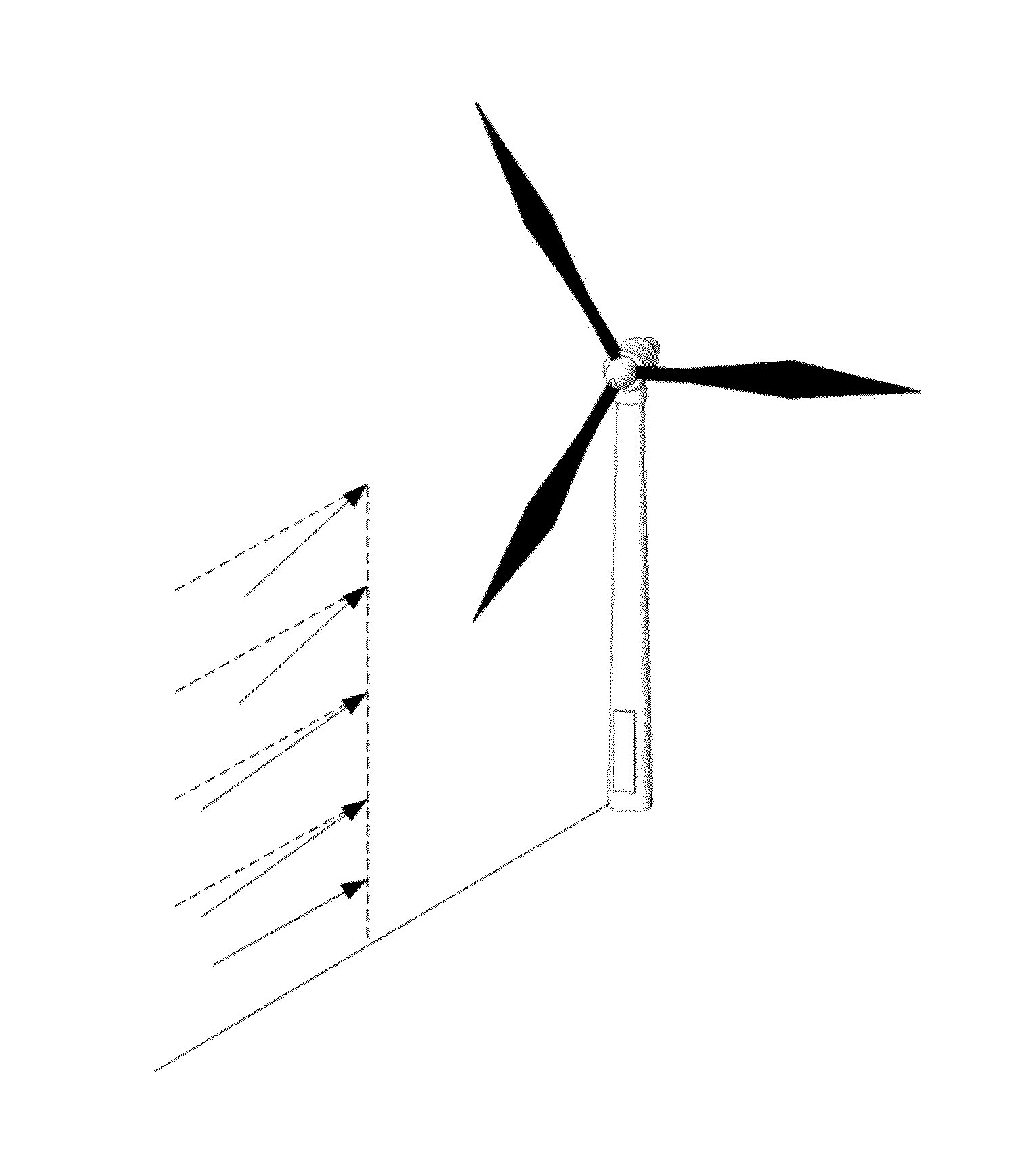
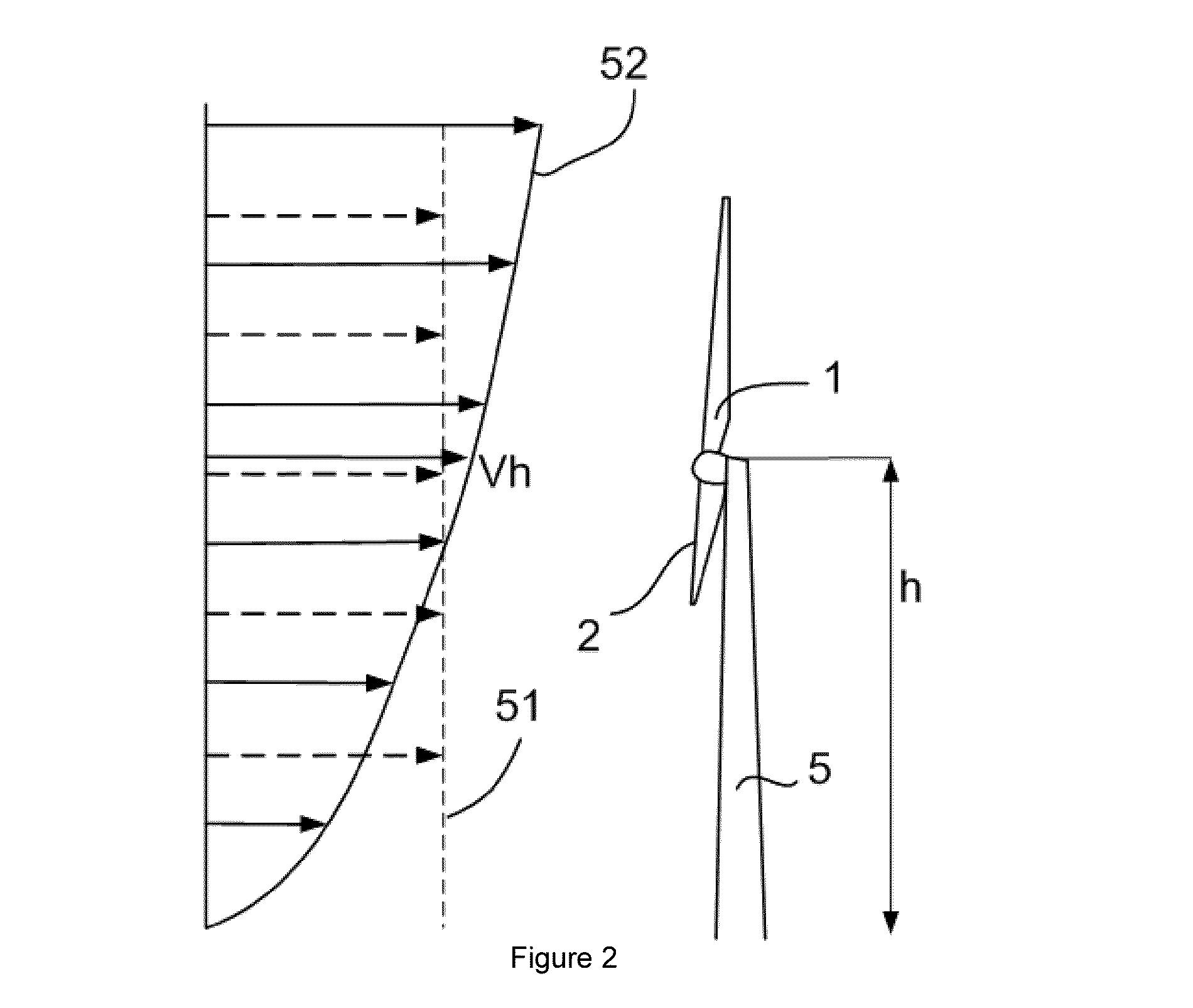
[0027]FIG. 2 illustrates the phenomenon of wind shear. A wind turbine comprising a tower 5 carrying a rotor with blades 1, 2 and a third non-visible blade is illustrated. The tower 5 has height h. At height h, the wind speed is Vh. This wind speed may be measured e.g. by an ...


PUM


Abstract

A method of operating a wind turbine having a rotor with a plurality of blades, and one or more pitch mechanisms for rotating the blades is disclosed. The method comprises a sub-nominal zone of operation and a supra-nominal zone of operation for wind speeds above the nominal wind speed. The sub-nominal zone of operation comprises a first, a second and a third operational range. The first operational range extends from a cut-in wind speed to a first wind speed, wherein the rotor speed is kept substantially constant at a first value. The second operational range extends from the first wind speed to a second wind speed, wherein both the rotor speed and generator torque are varied as a function of wind speed. The third operational range extends from the second wind speed to the nominal wind speed, wherein the rotor speed is kept substantially constant at a second value, and wherein in the second operational range, the generator torque, T, is determined in accordance with T=k·ω2, wherein ω is the generator speed and k is non-constant over the second operational range.

Description

[0001]This application claims the benefit of European Patent Application EP12382389.0 filed on Oct. 9, 2012 and U.S. Provisional Patent Application Ser. No. 61 / 735,496 filed Dec. 10, 2012, the disclosures of which are hereby incorporated by reference in their entirety for all purposes.[0002]The present disclosure relates to a method of operating a wind turbine, in particular a variable speed wind turbine.BACKGROUND ART[0003]Modern wind turbines are commonly used to supply electricity into the electrical grid. Wind turbines of this kind generally comprise a rotor with a rotor hub and a plurality of blades. The rotor is set into rotation under the influence of the wind on the blades. The rotation of the rotor shaft either directly drives the generator rotor (“directly driven”) or through the use of a gearbox.[0004]A variable wind speed turbine may typically be controlled by varying the generator torque and the pitch angle of the blades. As a result, aerodynamic torque, rotor speed and...

Claims


Application Information

Patent Timeline
Patent Type & Authority Applications(United States)
IPC IPC(8): F03D7/00
CPCF03D7/00F03D7/022F03D7/0224F03D7/0276F05B2270/1016F05B2270/32F05B2270/321Y02E10/72
Inventor GUADAYOL ROIG, MARC
Owner GE RENEWABLE TECH WIND BV
Why Eureka
Try Eureka