Magnetron

a magnetron and micro-magnetotron technology, applied in the field of magnets, can solve the problems of excessive significant increase in the material cost of the magnetron, and increase in the size of the magnetron, so as to reduce the size and reduce the output performance

Inactive Publication Date: 2006-10-05
LG ELECTRONICS INC
View PDF9 Cites 7 Cited by
  • Summary
  • Abstract
  • Description
  • Claims
  • Application Information

AI Technical Summary

Benefits of technology

[0010] An object of the present invention is to provide a magnetron,

Problems solved by technology

Meanwhile, since magnets mounted in the magnetron are made of a permanent magnetic material, material costs for the magnetron are increased.
In particular, a conventional magnetron has a problem in that, as the magnets and upper/lower magnetic poles are excessively large, the material costs are significantly increased.
Additiona

Method used


Image

  • Magnetron
  • Magnetron
  • Magnetron

Examples


Embodiment Construction

[0021] Reference will now be made in detail to the preferred embodiments of the present invention, examples of which are illustrated in the accompanying drawings. Wherever possible, the same reference numbers will be used throughout the drawings to refer to the same or like parts.

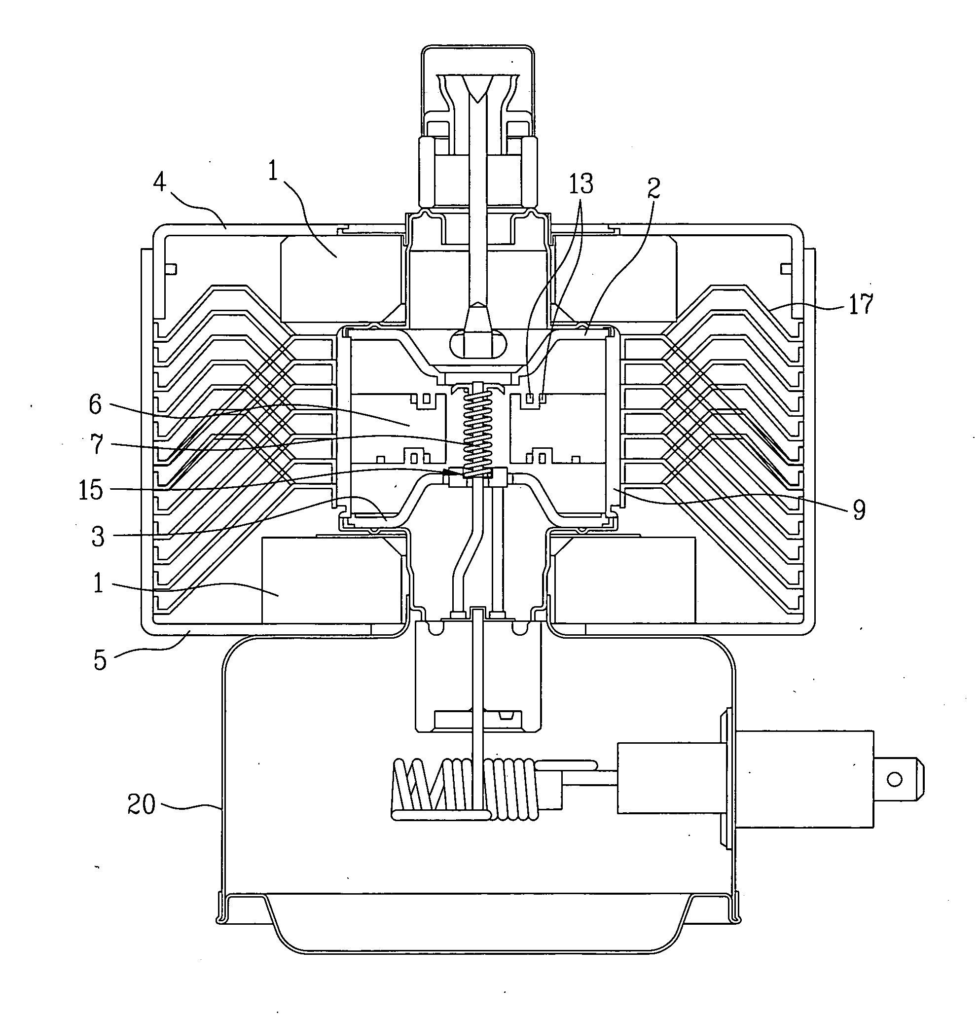
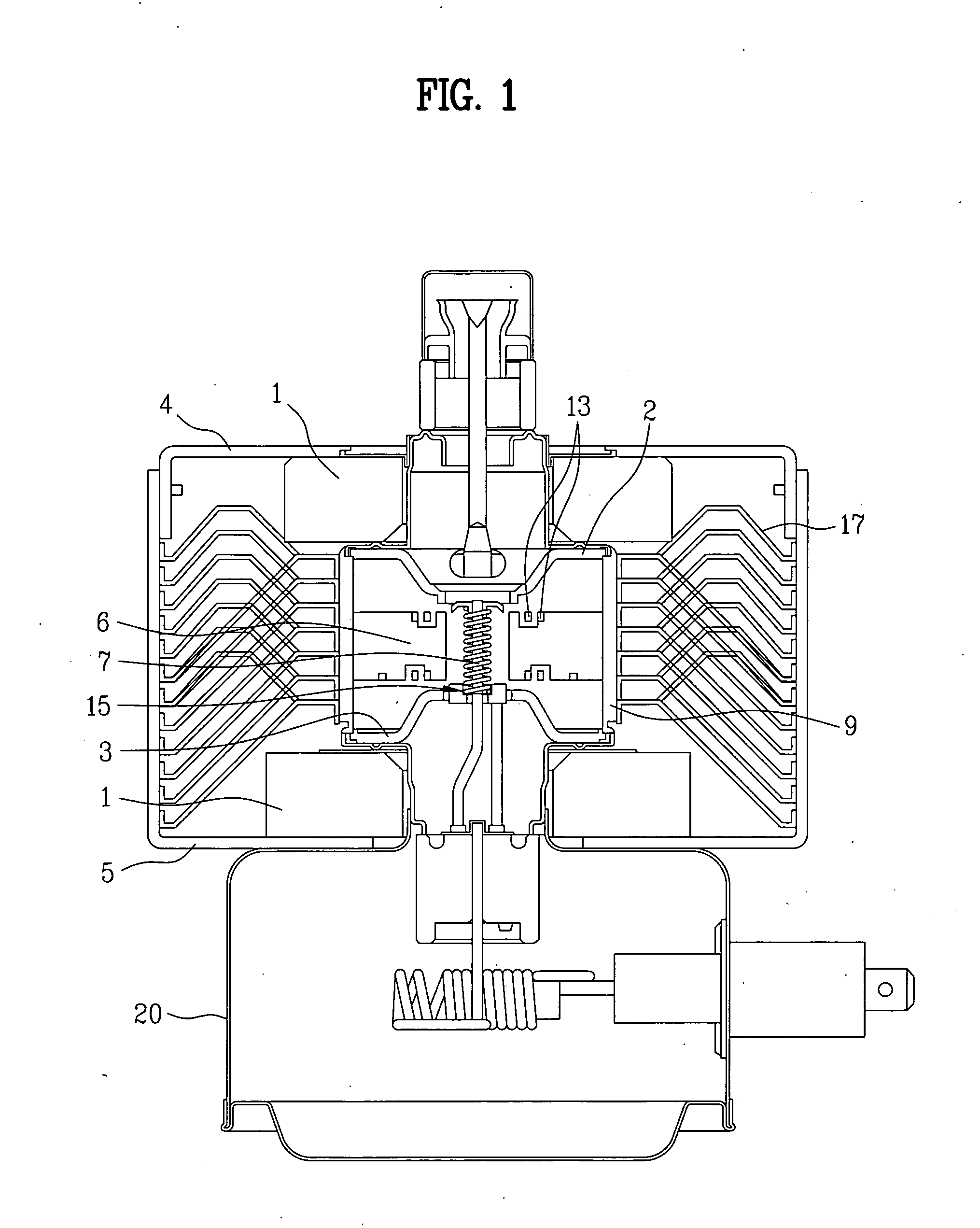
[0022]FIG. 1 is a cross-sectional view illustrating a magnetron according to the present invention.

[0023] As shown in FIG. 1, the magnetron comprises an anode cylinder 9, anode vanes 6, inner / outer straps 13, a cathode 15, a plurality of cooling fins 17, yokes 4 and 5, magnets 1, and a filter box 20.

[0024] The anode cylinder 9 has a cylindrical shape, and the anode vanes 6 are radially equipped into an inner wall of the anode cylinder 9 to constitute a resonant cavity. The inner / outer straps 13 are alternately arranged on upper and lower surfaces of the anode vanes 6 to electrically connect the vanes, and the cathode 15 includes a spiral filament 7 centered in the magnetron and acting as a negative elect...


PUM

PropertyMeasurementUnit
Lengthaaaaaaaaaa
Lengthaaaaaaaaaa
Lengthaaaaaaaaaa

Abstract

Disclosed herein is a magnetron. The magnetron comprises an anode cylinder, upper and lower magnets provided to upper and lower portions of the anode cylinder, and upper and lower magnetic poles connected to the magnets, respectively. Each of the magnets has an inner diameter of 19˜21 mm, a thickness of 11.5˜12.5 mm, and an outer diameter of 50˜54 mm.

Description

[0001] This application claims the benefit of Korean Patent Application No. 2005-026041, filed on Mar. 29, 2005, which is hereby incorporated by reference as if fully set forth herein. BACKGROUND OF THE INVENTION [0002] 1. Field of the Invention [0003] The present invention relates to a magnetron, and more particularly, to a miniaturized magnetron. [0004] 2. Discussion of the Related Art [0005] Generally, a magnetron is an oscillation source of microwaves for heating foods, and is utilized for microwave ovens and the like due to its simple construction and highly efficient stable behavior. [0006] Meanwhile, since magnets mounted in the magnetron are made of a permanent magnetic material, material costs for the magnetron are increased. In particular, a conventional magnetron has a problem in that, as the magnets and upper / lower magnetic poles are excessively large, the material costs are significantly increased. Additionally, the excessively large volumes of the magnet and the poles ...

Claims


Application Information

Patent Timeline
IPC IPC(8): C23C14/00
CPCH01J25/587H01J23/10H01J23/12
Inventor BAEK, CHAE HYUNLEE, JONG SOOLEE, YONG SOO
Owner LG ELECTRONICS INC
Why Eureka
Try Eureka