Machining fluid level detection device for wire cut electrical discharge machines

a detection device and wire-cutting technology, applied in the direction of electrical-based machining apparatus, metal-working apparatus, manufacturing tools, etc., can solve the problems of preventing the operation of the machine, accumulating a large amount of sludge, and remaining sludge produced

Active Publication Date: 2006-10-05
FANUC LTD
View PDF7 Cites 9 Cited by
  • Summary
  • Abstract
  • Description
  • Claims
  • Application Information

AI Technical Summary

Benefits of technology

[0016] According to the present invention, the table and / or machining tank is used as an electrode which faces the electrode attached via an insulating plate to the upper guide, so that there are no moving parts in the machining fluid level detecting means that come into direct contact with the machining fluid. Consequently, sludge does not affect the machining fluid level detecting means and does not clog the gap between the electrodes, either. Further, the signal wire and other parts are not damaged due to electric corrosion by the machining fluid. Thus, the machining fluid level can be detected reliably without the undesired effects of sludge in the machining fluid.

Problems solved by technology

In the machining tank, however, there remains sludge produced by electrical discharge machining.
A large amount of sludge accumulates, especially after continuous rough machining.
The sludge adheres to moving parts in the float switch and may prevent their operation.
In addition, for structural reasons, the signal wire of the float switch is also immersed in the machining fluid, so the signal wire is eventually broken due to electric corrosion by the machining fluid.
As described above, conventional machining fluid level detection methods using a float switch are unreliable because the float switch may malfunction due to sludge or the signal wire may be broken due to electrical corrosion by the machining fluid.
Because the electrodes are placed inside the machining tank, enlarged electrodes would limit the size of the workpiece, or might be hit and damaged by the workpiece.
Such a narrow space between the electrodes can lead to false detection due to current flowing between the electrodes through a droplet held therebetween by surface tension after the machining fluid is discharged from the machining tank and the machining fluid level is quite low.
In such a case, current flows between the electrodes even after the machining fluid has been discharged from the machining tank and the machining fluid level is quite low, which may cause false detection.

Method used


Image

  • Machining fluid level detection device for wire cut electrical discharge machines
  • Machining fluid level detection device for wire cut electrical discharge machines

Examples


Embodiment Construction

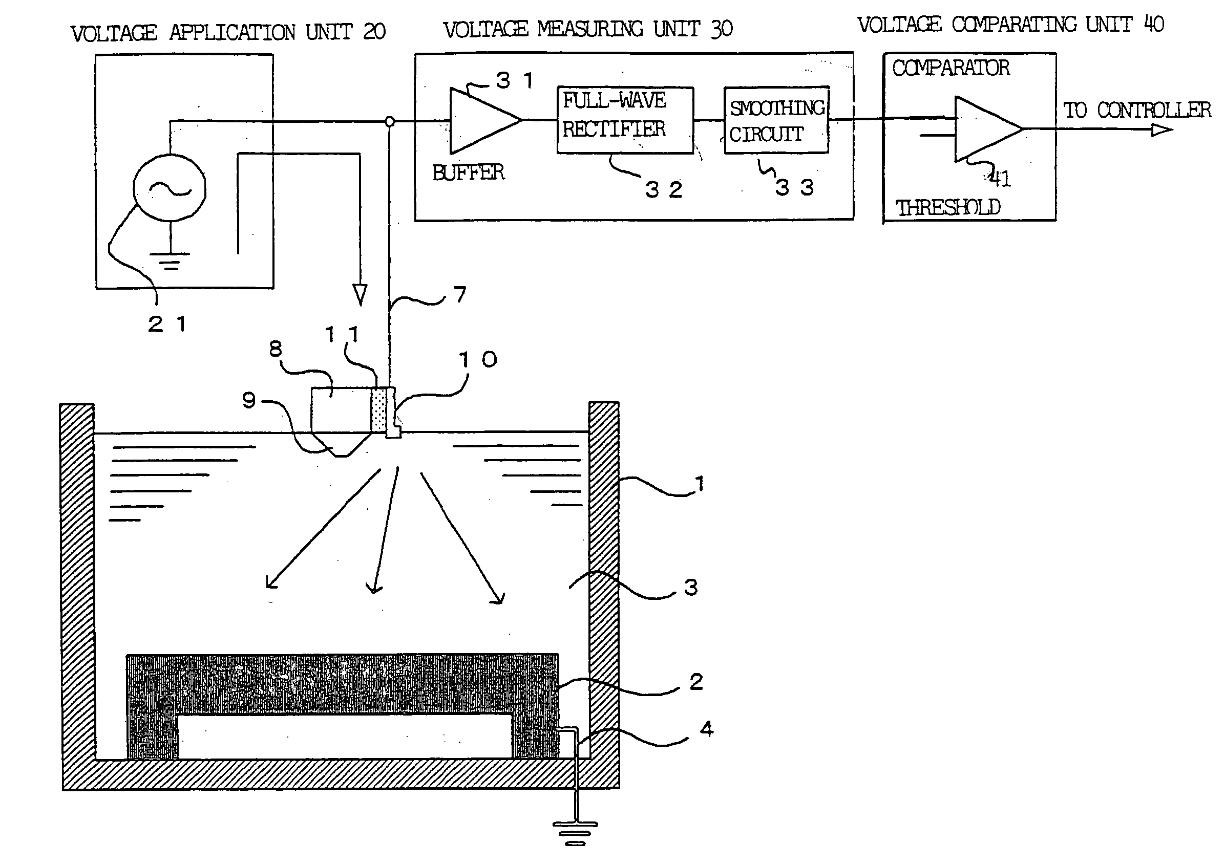
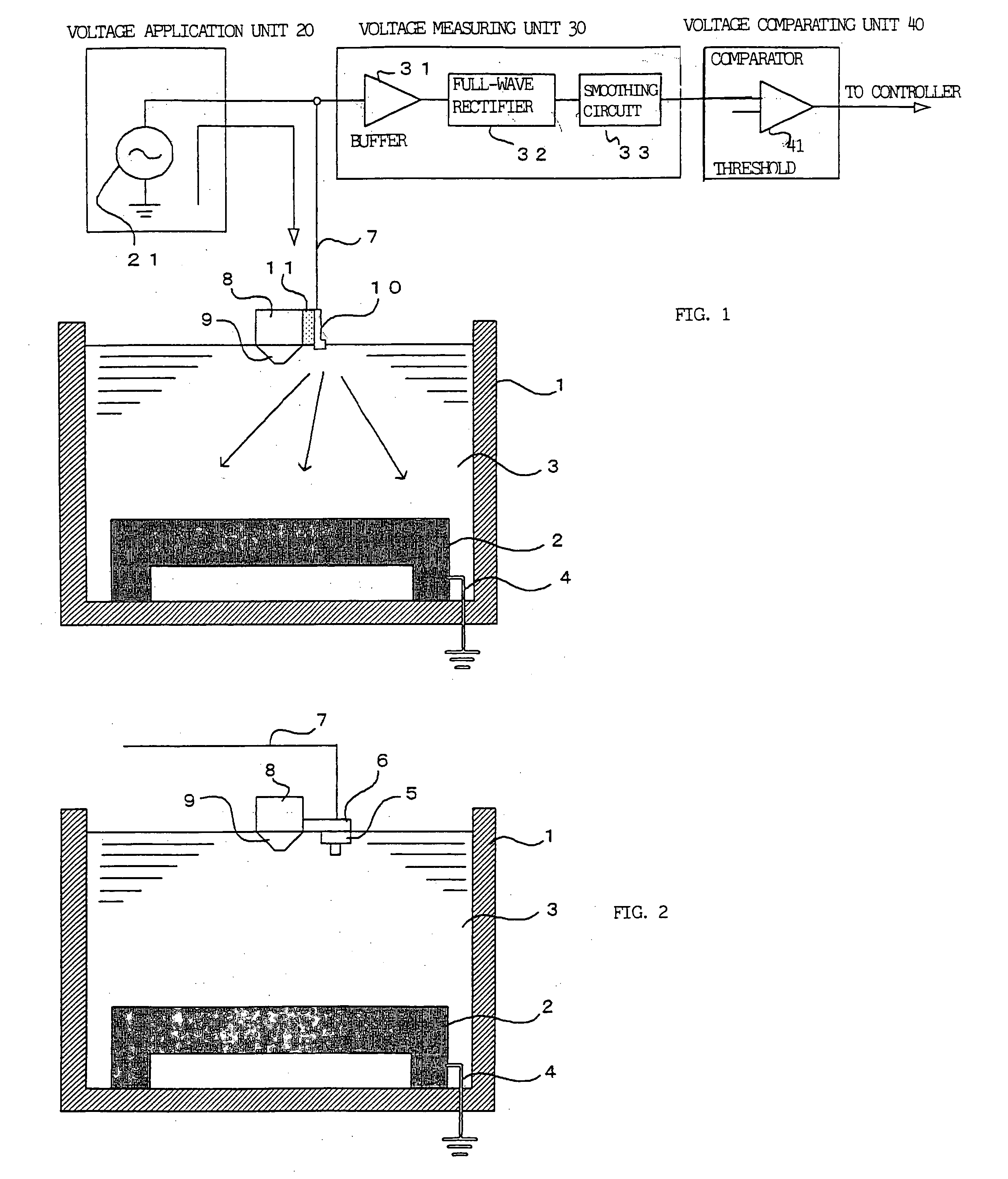
[0019]FIG. 1 schematically shows a machining fluid level detection device for wire cut electrical discharge machining according to an embodiment of the present invention. In this figure, elements identical to elements in the conventional device shown in FIG. 2 are indicated by the same reference numerals.

[0020] A machining tank 1 has a table 2 disposed therein for mounting a workpiece. The table 2 is grounded through a ground wire 4. An electrode 10 is attached via an insulating plate 11 to an upper guide 8 guiding a wire electrode. A signal wire 7 is connected to electrode 10. The upper guide 8 is provided with a nozzle 9.

[0021] The signal wire 7 is connected to a voltage application unit 20. In this embodiment, the voltage application unit 20 comprises an AC constant current source. A voltage measuring unit 30 is connected to the signal wire 7 between the voltage application unit 20 and the electrode 10. A voltage comparing unit 40 is connected to the voltage measuring unit 30. ...


PUM

PropertyMeasurementUnit
distanceaaaaaaaaaa
voltageaaaaaaaaaa
heightaaaaaaaaaa

Abstract

A table for placing a workpiece is grounded. An electrode for detecting machining fluid level is attached to an upper guide that guides the wire electrode, with the electrode insulated from the upper guide. A voltage is applied to the electrode, and the voltage between the electrode and the grounded table is detected and compared with a threshold value to determine whether the machining fluid level has reached a predetermined height.

Description

BACKGROUND OF THE INVENTION [0001] 1. Field of the Invention [0002] The present invention relates to a machining fluid level detection device for wire cut electrical discharge machines. [0003] 2. Description of the Related Art [0004] Many wire cut electrical discharge machines are designed to perform machining on a workpiece immersed in an electrically conductive water-based machining fluid stored in a machining tank. The machining fluid is supplied to the machining tank before electrical discharge machining starts. The machining fluid level must be kept at a predetermined height in the machining tank. A float switch is usually used to detect the machining fluid level. [0005]FIG. 2 schematically shows a conventional machining tank using a float switch to detect the machining fluid level. Referring to FIG. 2, the machining tank 1 has a table 2 disposed therein for mounting a workpiece. Machining tank 1 stores machining fluid 3. A ground wire 4 is connected to table 2. [0006] A float ...

Claims


Application Information

Patent Timeline
Patent Type & Authority Applications(United States)
IPC IPC(8): B23H7/02
CPCB23H7/36B23H1/10
Inventor KAWAHARA, AKIYOSHIFURUTA, TOMOYUKI
Owner FANUC LTD
Why Eureka
Try Eureka