Laminated core testing device

a technology of laminated cores and testing devices, which is applied in the direction of optical radiation measurement, process and machine control, instruments, etc., can solve the problems of damage to laminated cores or stators, damage to laminated cores, and damage to stators, so as to reduce the physical size facilitate transportation of laminated core testing arrangements

Active Publication Date: 2006-10-05
SIEMENS ENERGY GLOBAL GMBH & CO KG
View PDF10 Cites 11 Cited by
  • Summary
  • Abstract
  • Description
  • Claims
  • Application Information

AI Technical Summary

Benefits of technology

[0021] Owing to an embodiment in which the field winding has at least two lines, it is possible to decrease the physical size of the l

Problems solved by technology

Faults may be damage in the rotor winding or damage in the stator.
In the stator, damage may occur, inter alia, in the laminated cores or in the stator winding.
The insulation betwee

Method used


Image

  • Laminated core testing device
  • Laminated core testing device
  • Laminated core testing device

Examples


Embodiment Construction

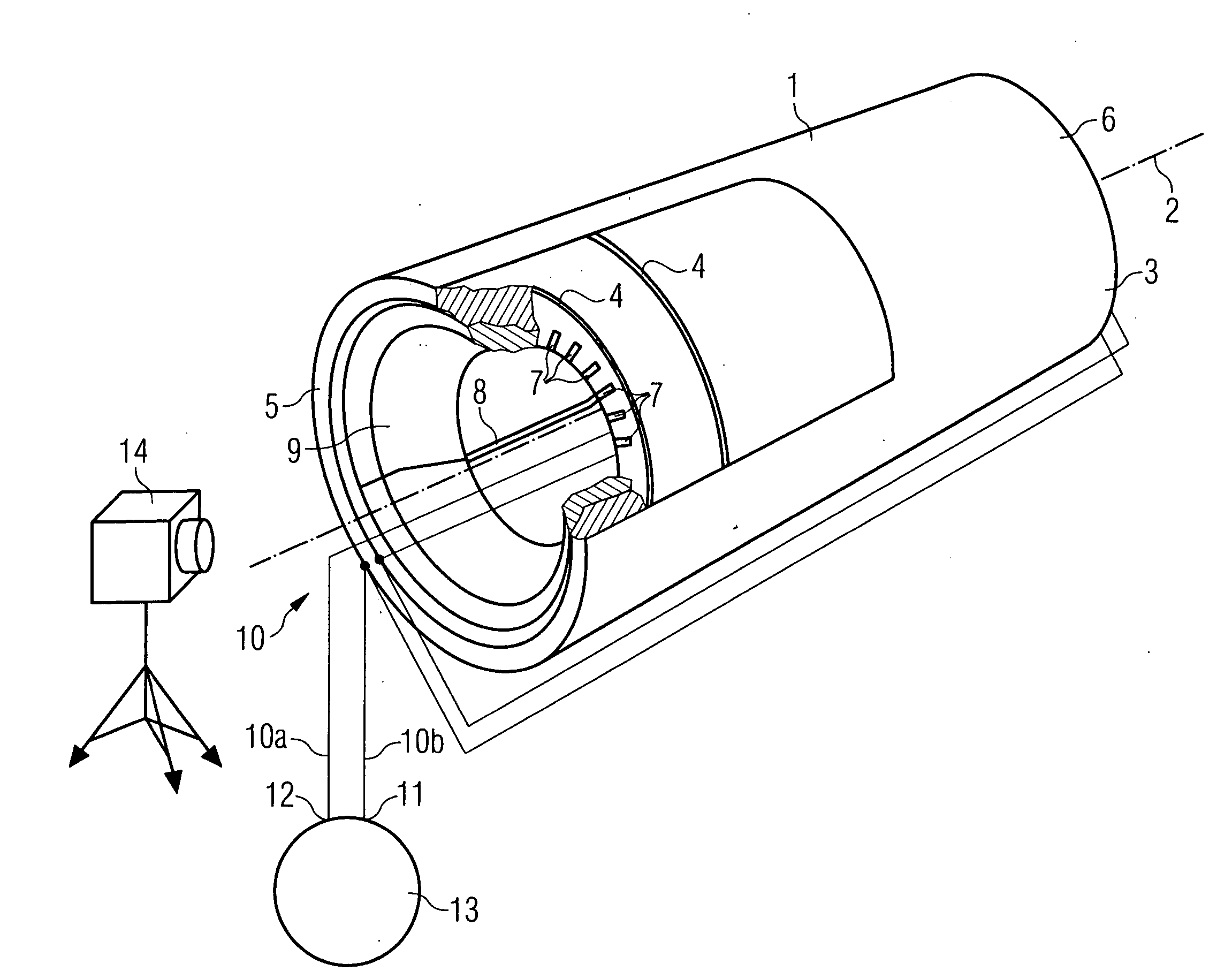
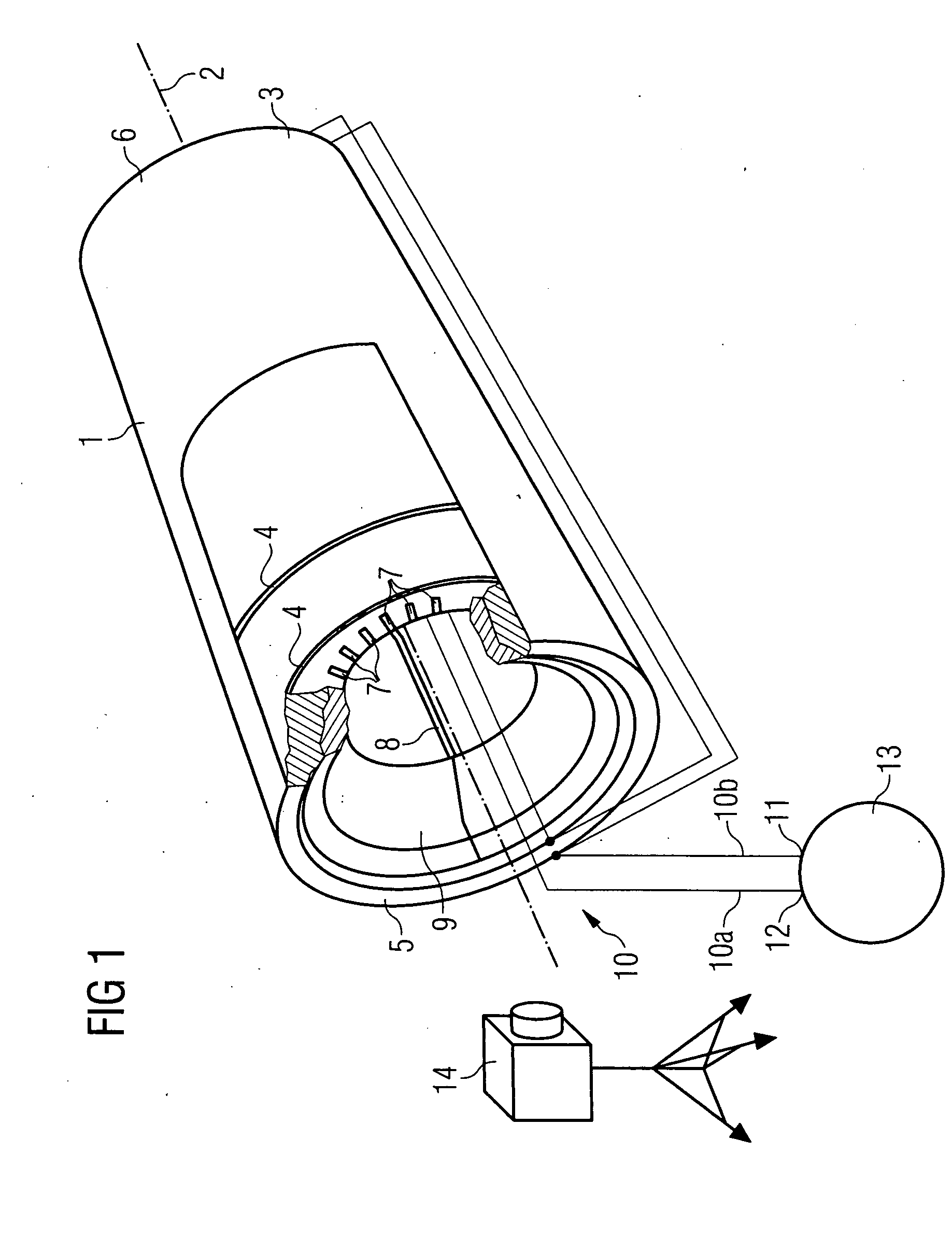
[0025]FIG. 1 illustrates the design of a laminated core testing arrangement. A generator (not completely illustrated) has a stator 1. The stator 1 is designed to be symmetrical with respect to an axis of rotation 2. The stator 1 has an outer housing 3. Laminated cores 4 are arranged perpendicularly and symmetrically with respect to the axis of rotation 2. For reasons of clarity, only two laminated cores 4 are illustrated in FIG. 1. The laminated cores 4 are arranged within the outer housing 3 from a stator start 5 to a stator end 6. The laminated cores 4 are fixed in the direction of the axis of rotation 2 in a manner which is not illustrated in more detail.

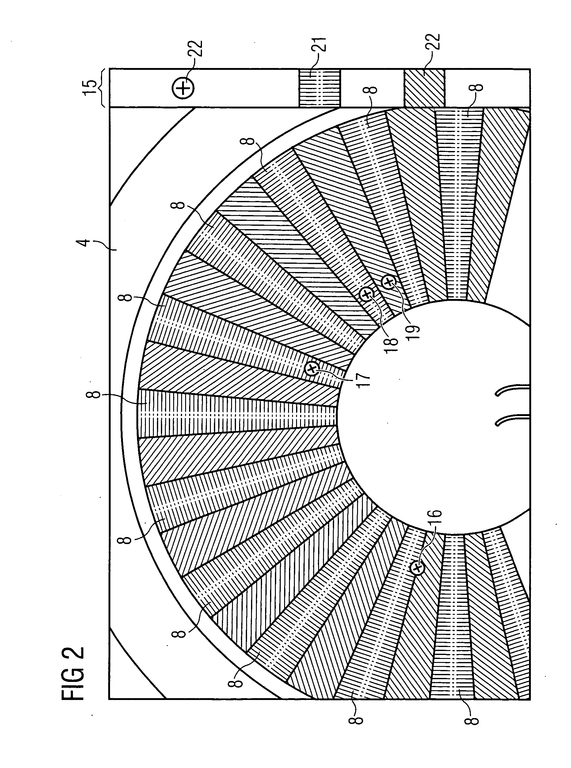
[0026] The laminated cores 4 have two or more slots 7 which are arranged symmetrically in the circumferential direction of the outer housing 3. A stator winding, which is formed from two or more stator winding bars 8, is arranged in the slots 7 of the laminated cores 4 in a manner which is not illustrated in any more detail. For...


PUM


Abstract

The invention relates to a laminated core testing device for testing laminated cores in a generator. To this end, the laminated core testing device comprises an exciting winding, which is situated parallel to a rotation axis of the generator and which is connected to a secondary alternating current generator, and comprises an infrared image acquisition device, which is designed for acquiring infrared recordings. Said secondary alternating current generator has a controllable frequency converter, and the secondary alternating current generator, at a frequency ranging from 400 to 600 Hz, provides, in a single-phase manner, an output of 200 kW with a controllable output voltage ranging from 0 to 3.0 kV.

Description

CROSS REFERENCE TO RELATED APPLICATION [0001] This application is the US National Stage of International Application No. PCT / DE2003 / 004185, filed Dec. 18, 2003 and claims the benefit thereof. The International Application claims the benefits of German Patent application No. 10311182.4 DE filed Mar. 12, 2003, both of the applications are incorporated by reference herein in their entirety.FIELD OF THE INVENTION [0002] The invention relates to a laminated core testing arrangement for the purpose of testing laminated cores in a generator, the laminated core testing arrangement having a field winding, which lies in parallel with an axis of rotation of the generator and is connected to a high-voltage testing device producing alternating current, as well as an infrared image detection device which is designed to detect infrared radiation. [0003] The invention also relates to a method for testing for faults in a stator of a generator, a high-voltage testing device producing alternating curr...

Claims


Application Information

Patent Timeline
IPC IPC(8): G01J5/00G01R31/308G01R31/34H02K15/00
CPCG01R31/308H02K15/00G01R31/34
Inventor BACA, MATTHIASHASCHKE, PETERRICHTER, CLAUS-GEORGTWELLMANN, HANS-BERND
Owner SIEMENS ENERGY GLOBAL GMBH & CO KG
Why Eureka
Try Eureka