Pulse radar device

a pulse radar and radar technology, applied in the direction of measurement devices, using reradiation, instruments, etc., can solve the problem of adding high frequency noise to the output of a switching power source, and achieve the effect of improving the certainty of operation of the pulse radar device, effective prevention of malfunction, and high frequency nois

Inactive Publication Date: 2006-10-05
TDK CORPARATION
View PDF4 Cites 35 Cited by
  • Summary
  • Abstract
  • Description
  • Claims
  • Application Information

AI Technical Summary

Benefits of technology

[0019] By providing the control unit with the delay circuit and the radar control circuit so that the units in the radar module may operate based on the switching pulse the radar module can operate based on switching operations of the switching pulse. Accordingly, the switching pulse and the units in the radar module are all synchronized in operation timing, to improve the certainty of oper...

Problems solved by technology

On the rising edge or the trailing edge of a switching pulse, high frequency noise ma...

Method used


Image

  • Pulse radar device
  • Pulse radar device
  • Pulse radar device

Examples


first embodiment

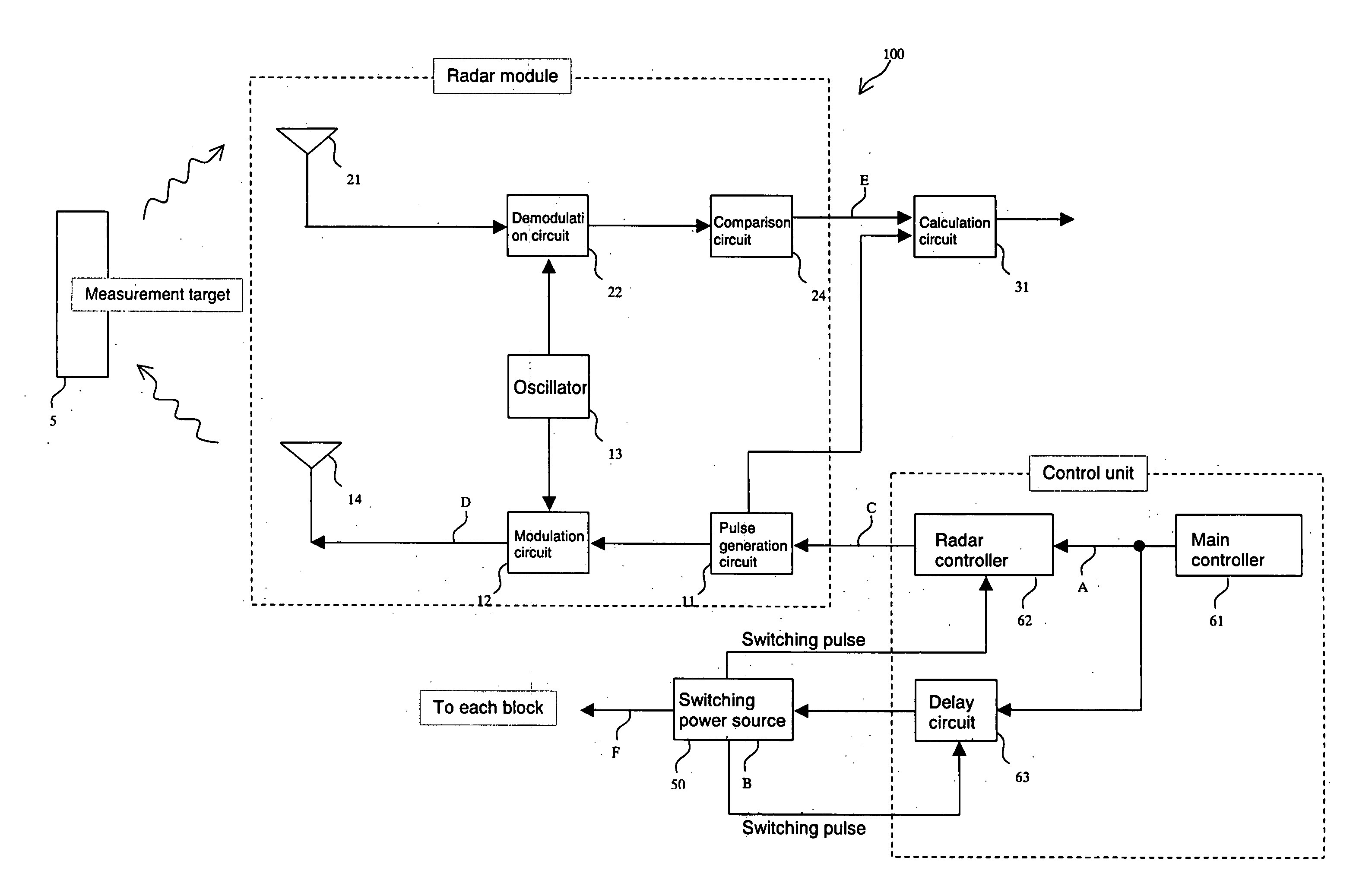
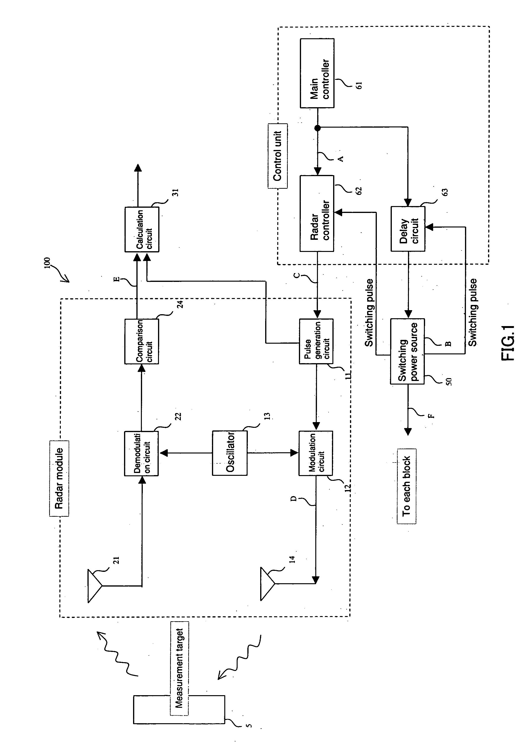
[0037]FIG. 1 is an explanatory block diagram of the first embodiment of a pulse radar device related to the present invention, showing a configuration of the pulse radar device. In FIG. 1, a reference numeral 11 indicates a pulse generation circuit for generating a transmitted pulse, a reference numeral 12 indicates a modulation circuit for modulating an amplitude of a transmitted pulse at a modulation frequency, a reference numeral 13 indicates an oscillator that oscillates at a modulation frequency, a reference numeral 14 indicates a transmitting antenna for transmitting a transmitted pulse wave, a reference numeral 21 indicates a receiving antenna for receiving a reflected wave from a measurement target 5, a reference numeral 22 indicates a demodulation circuit for demodulating a reflected wave, a reference numeral 24 indicates a comparison circuit for comparing a demodulated pulse from a demodulation circuit 22 to a predetermined threshold value to output a received pulse, a ref...

second embodiment

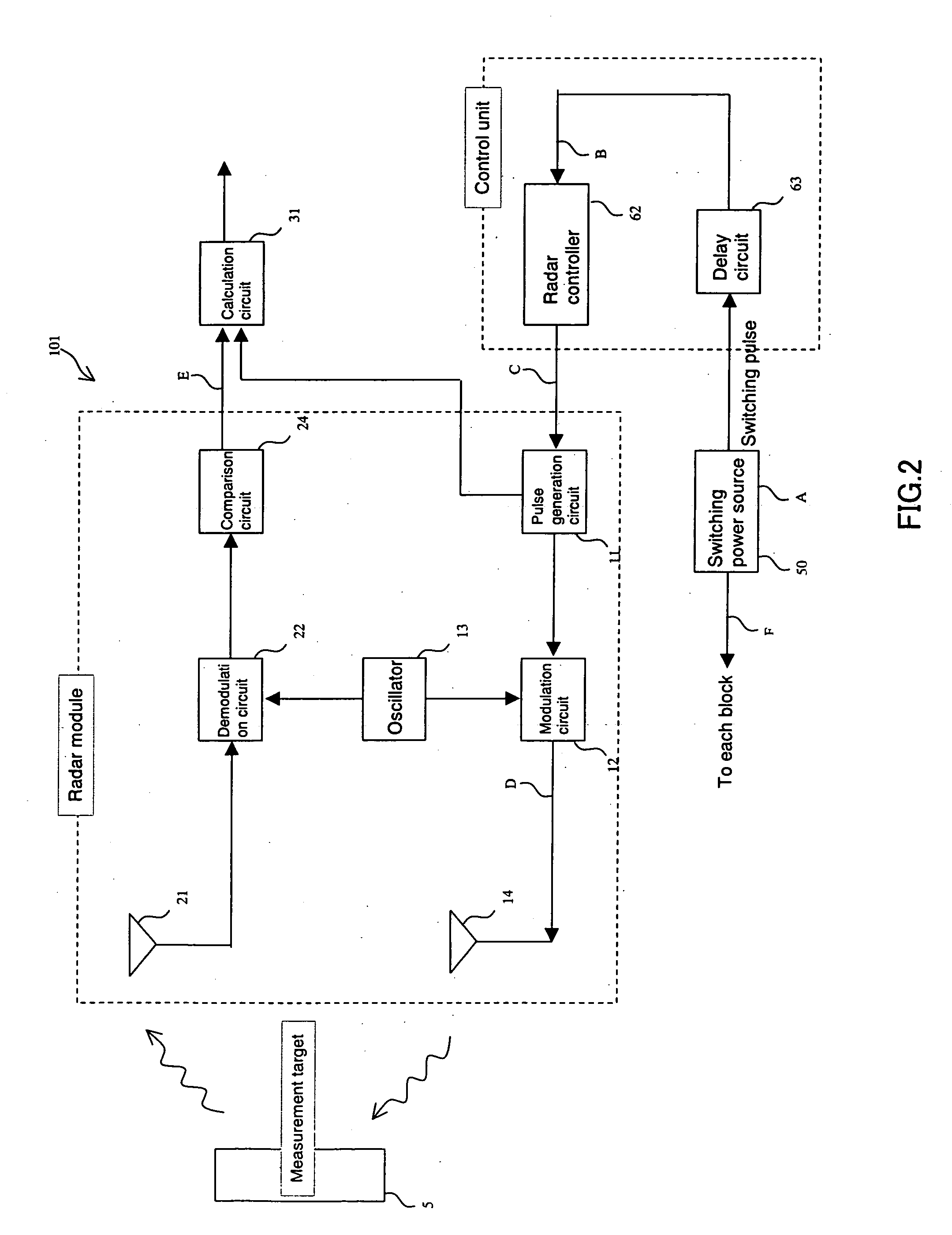
[0073]FIG. 3 is an explanatory block diagram of a second embodiment of a pulse radar device related to the present invention, showing a configuration of the pulse radar device. In FIG. 3, the same reference symbols as those of FIG. 1 indicate the same components. In the present embodiment, a control signal output from a control unit is input to a demodulation circuit 22 or a comparison circuit 24, to control operations of a reception unit. In the following, operations of the control unit are described with reference to FIG. 12, FIGS. 12(A), 12(B), 12(C), 12(D), 12(E), and 12(F) each show one example of a signal waveform that appears at points A, B, C, D, E, and F shown in FIG. 3 respectively. In the following description, the reference symbols shown in FIG. 3 are used appropriately.

[0074]FIG. 12(A) shows a timing of a reference signal output from a main controller 61. FIG. 12(B) shows a timing of a switching pulse generated in a switching power source 50. The switching pulse is gen...

third embodiment

[0097]FIG. 5 is an explanatory block diagram of one example of the second embodiment of a pulse radar device related to the present invention, showing a configuration of the pulse radar device. In FIG. 5, the same reference symbols as those of FIG. 1 indicate the same components. In the present embodiment, a control signal output from a control unit is input to a calculation circuit 31, to control operations of a calculation unit. As shown in FIG. 5, a radar module includes the above described transmission unit, reception unit, and calculation unit. In the following, operations of the control unit are described with reference to FIG. 14, FIGS. 14(A), 14(B), 14(C), 14(D), 14(E), and 14(F) each show one example of a signal waveform that appears at points A, B, C, D, E, and F shown in FIG. 5 respectively. In the following description, the reference symbols shown in FIG. 5 are used appropriately.

[0098]FIG. 14(A) shows a timing of a reference signal output from a main controller 61. FIG...


PUM


Abstract

The present invention provides a pulse radar device comprising a radar module that includes a transmission unit which transmits a transmitted pulse wave obtained by modulating a transmitted pulse and a reception unit receives a reflected wave of said transmitted pulse wave reflected by a measurement target and demodulates said reflected wave to thereby generate a received pulse, a switching power source which generates drive power for said radar module by switching DC power by turning a switching pulse on and off, and a control unit which controls operations of said radar module so that a process from transmission of said transmitted pulse wave to generation of said received pulse may be completed in a period during which said switching pulse is in an on-state except a predetermined period measured from rising edge of said switching pulse or a period during which said switching pulse is in an off-state except the predetermined period measured from trailing of said switching pulse.

Description

BACKGROUND OF THE INVENTION [0001] 1. Field of the Invention [0002] The present invention relates to a pulse radar device for detecting a measurement target by transmitting a transmitted pulse wave thereto. [0003] 2. Description of the Related Art [0004] Conventionally a pulse radar device has been available which transmits a transmitted pulse wave to a measurement target and receives a reflected wave therefrom to thereby detect a distance thereto. This type of pulse radar device is installed in, for example, a vehicle to avoid its collision with an obstacle. In this case, power is supplied to the pulse radar device by matching an input voltage from a switching type of power source such as a vehicle battery or a cell. [0005] A switching type is employed as DC power source for the pulse radar device owing to a request for compacting it. A switching type of switching power source converts an AC voltage or DC voltage into a high frequency AC voltage by using a switching pulse generated...

Claims


Application Information

Patent Timeline
IPC IPC(8): G01S13/00G01S13/931
CPCG01S7/28G01S13/931G01S7/292
Inventor IKEDA, HIROSHI
Owner TDK CORPARATION
Why Eureka
Try Eureka