Liquid crystal display and driving method thereof

a technology of liquid crystal display and driving method, which is applied in the direction of static indicating devices, non-linear optics, instruments, etc., can solve the problems of poor image quality and insufficient charge of the pixel supplied with a data signal having reversed polarity

Inactive Publication Date: 2006-10-05
LEE SEUNG WOO
View PDF7 Cites 15 Cited by
  • Summary
  • Abstract
  • Description
  • Claims
  • Application Information

AI Technical Summary

Benefits of technology

[0012] An object of the present invention is to adjust pulse width of gate signals depending on load of data lines. Another object of the present invention is to remove the flicker of an LCD driven in one-dot inversion. In addition, the present invention has another object to change the inversion type when the vertical frequency of the LCD changes.

Problems solved by technology

If the pulse width of the gate signal is reduced and the load of the data lines is large, a pixel supplied with a data signal having reversed polarity is not sufficiently charged due to the heavy load of the data line.
This charging inequality results in the horizontal line pattern causing poor image quality.

Method used


Image

  • Liquid crystal display and driving method thereof
  • Liquid crystal display and driving method thereof
  • Liquid crystal display and driving method thereof

Examples


first embodiment

[0030] First, an LCD according to the present invention will be described with reference to FIGS. 1 and 3.

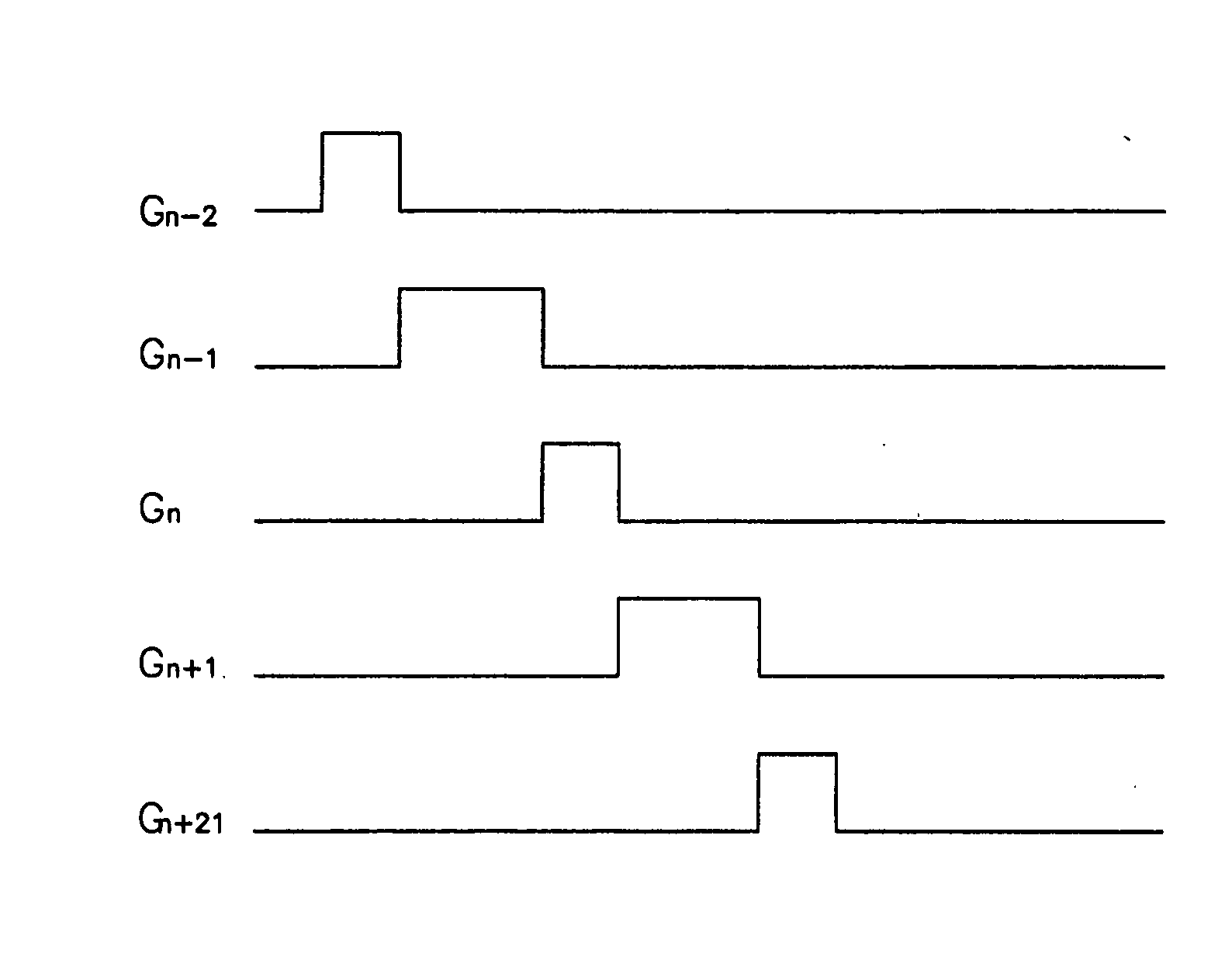
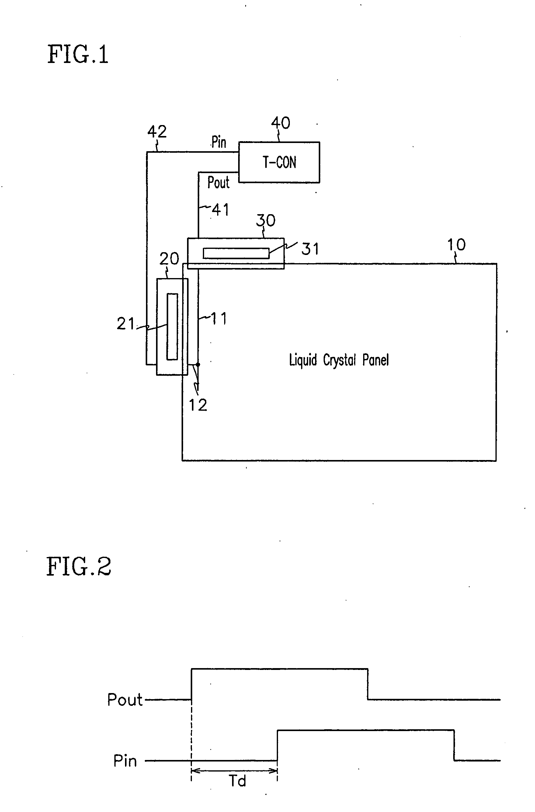
[0031]FIG. 1 is a schematic layout diagram of an LCD according to the first embodiment of the present invention. FIG. 2 is a diagram showing waveforms of pulses used for measuring load of a data line according to the first embodiment of the present invention, and FIG. 3 is a diagram showing waveforms of gate signals having pulse widths adjusted according to the first embodiment of the present invention.

[0032] Referring to FIG. 1, an LCD according to the first embodiment of the present invention includes a liquid crystal panel 10, gate and data tape carrier packages (“TCPs”) 20 and 30 connected to upper and left ends of the liquid crystal panel 10, respectively, and a timing controller (“T-CON”) 40 connected to the TCPs 20 and 30 via respective lid lines (not shown).

[0033] A plurality of gate lines (not shown) transmitting scanning signals or gate signals extending in a transve...

second embodiment

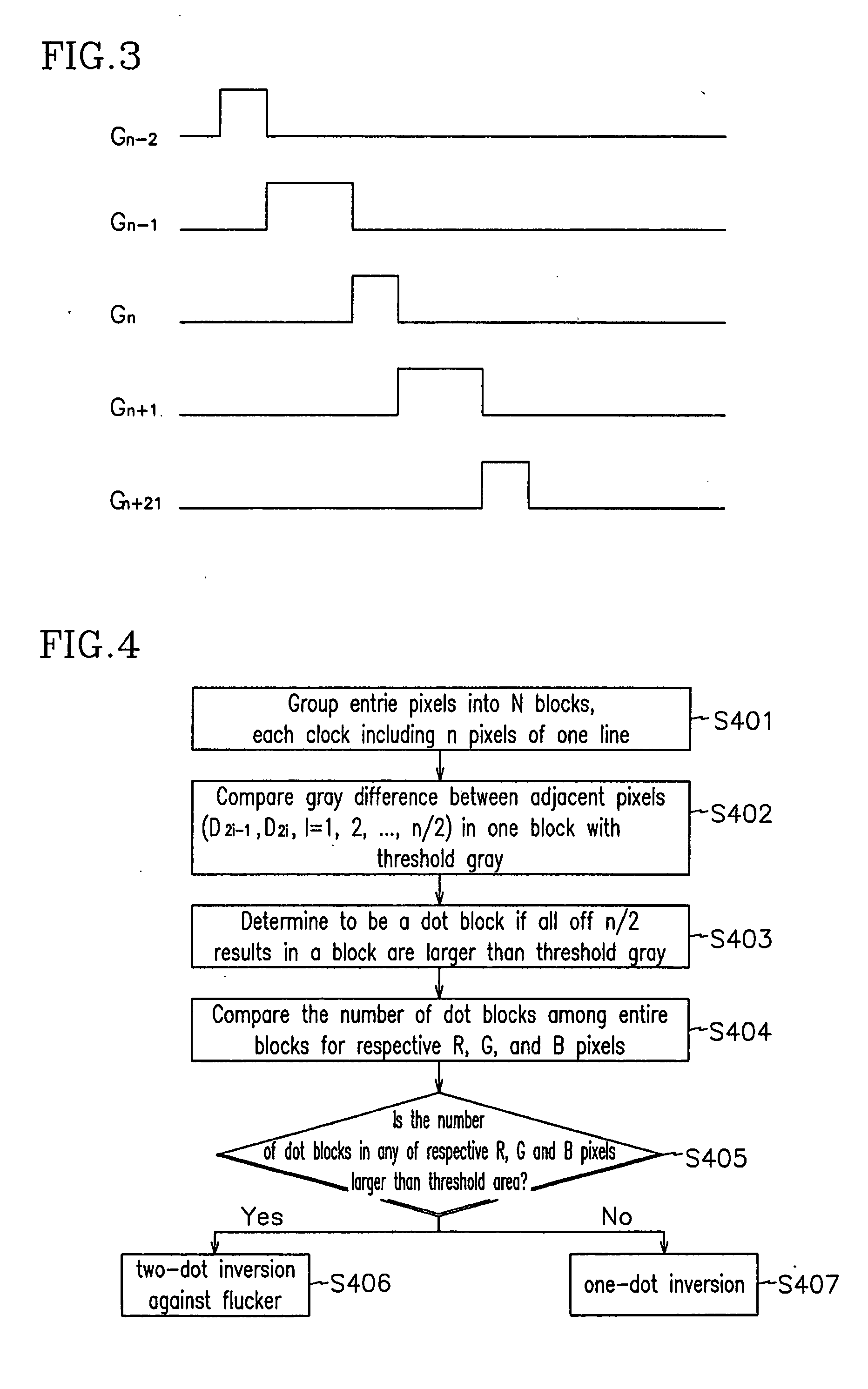
[0044] First, a second embodiment, which drives an LCD in one-dot inversion with high frequency and changes the inversion type into two-dot inversion upon the generation of flicker, is described with reference to FIG. 4.

[0045]FIG. 4 is a flowchart illustrating a driving method of an LCD according to the second embodiment of the present invention.

[0046] The second embodiment of the present invention uses one-dot inversion for an LCD driven with a frequency equal to or higher than 60 Hz such as 75 Hz. If the LCD is driven with a frequency higher than 60 Hz, flicker can be generated as shown in FIG. 7. In case that the flicker is generated, the conversion of the inversion type of the LCD into two-dot inversion avoids the deterioration of the image quality.

[0047] Now, it will be described in detail. As shown in FIG. 4, the timing controller 40 of the LCD according to the second embodiment of the present invention groups the entire pixels in the liquid crystal panel 10 into N blocks of...

third embodiment

[0054]FIG. 5 is a flowchart illustrating a driving method of an LCD according to the present invention.

[0055] The third embodiment of the present invention drives the LCD in two-dot inversion for 60 Hz frequency while in one-dot inversion for higher frequency such as 75 Hz. Since an LCD is usually driven with 60 Hz frequency, two-dot inversion driving of the LCD with 60 Hz frequency reduces power consumption. If the flicker is generated for the frequencies higher than 60 Hz, then the inversion type is changed into two-dot inversion to avoid the deterioration of the display quality as in the second embodiment of the present invention.

[0056] Now, it will be described in more detail. As shown in FIG. 5, the timing controller 40 of an LCD according to the third embodiment of the present invention determines whether the vertical driving frequency of the LCD is changed (S501). The determination of the frequency change is based on an internal clock of the timing controller 40 or an extern...


PUM

PropertyMeasurementUnit
vertical frequencyaaaaaaaaaa
frequencyaaaaaaaaaa
frequencyaaaaaaaaaa

Abstract

The present invention provides an LCD capable of being driven with various frequencies without deterioration of image quality. According to the present invention, a method of driving an LCD in two-dot inversion for a low vertical frequency and in one-dot inversion for a high vertical frequency is provided. The method determines whether the vertical frequency of the LCD changes, changes the inversion type into one-dot inversion if the vertical frequency is changed from a low frequency to a high frequency, and changes the inversion type into two-dot inversion if the vertical frequency is changed from a high frequency to a low frequency. Moreover, if a flicker is generated when driving in one-dot inversion, the inversion type is changed into two-dot inversion. To avoid the unequal charging generated in the LCD driven in two-dot inversion, the pulse width of the gate signals are adjusted after measuring the load of the data line.

Description

BACKGROUND OF THE INVENTION [0001] (a) Field of the Invention [0002] The present invention relates to a liquid crystal display and a driving method thereof. [0003] (b) Description of Related Art [0004] A liquid crystal display (LCD) includes an upper panel provided with a common electrode and color filters, a lower panel provided with thin film transistors (TFTs) and pixel electrodes, and a liquid crystal layer interposed between alignment layers of the panels. The LCD displays images by controlling light transmittance, and the control of the light transmittance is performed by applying voltages to the pixel electrodes and the common electrode to generate electric fields which change the arrangement of liquid crystal molecules. [0005] One-dot inversion and two-dot inversion is used for driving the LCD. Both of one-dot and two-dot inversion apply a data signal in a frame having a polarity opposite that of a data signal in a previous frame. [0006] One-dot inversion applies a data sign...

Claims


Application Information

Patent Timeline
Patent Type & Authority Applications(United States)
IPC IPC(8): G09G3/36G02F1/133G09G3/20
CPCG09G3/3614G09G2320/0247G09G3/3648G02F1/133
Inventor LEE, SEUNG-WOO
Owner LEE SEUNG WOO
Why Eureka
Try Eureka