Orifice plate protection device

a protection device and orifice plate technology, which is applied in printing and other directions, can solve the problems of clogging the nozzle and/or misdirecting fluid, weak cohesion strength of the psa with respect to the base film, and it is difficult to remove psa material that has swelled in the nozzle hole, so as to improve the removal of the backing film, less affinity, and less deterioration over time

Inactive Publication Date: 2006-10-05
FUNAI ELECTRIC CO LTD
View PDF6 Cites 20 Cited by
  • Summary
  • Abstract
  • Description
  • Claims
  • Application Information

AI Technical Summary

Benefits of technology

[0010] Another exemplary embodiment provides a micro-fluid ejection head attached to a fluid cartridge body. The micro-fluid ejection head has an orifice plate with a backing film and radiation curable adhesive applied to a surface of the office plate for sealing nozzle holes in the orifice plate. The adhesive is curable in a pattern sufficient to seal adjacent to nozzle holes in the orifice plate and to enhance removal of the backing film and adhesive from the orifice plate prior to use of the micro-fluid ejection head.
[0011] Advantages of exemplary embodiments described herein include, but are not limited to, an ability to adjust the amount of adhesion between a nozzle plate sealing tape and a nozzle plate of a fluid ejection device. Another advantage is that the tape may be removed from the nozzle plate with a minimum of residue left on the nozzle plate and in nozzle holes of the nozzle plate. Yet another advantage is that the cured adhesive may have less affinity for the fluids ejected through the nozzle holes and thus may exhibit less deterioration over time thereby improving the sealing capabilities of the tape.

Problems solved by technology

Another disadvantage of an acrylic based PSA cover tape is that a cohesive strength of the PSA is weak with respect to the base film.
When the tape is removed from the nozzle plate, the adhesive may be left in the nozzle holes causing a clogged nozzle and / or misdirected fluid.
As the nozzle holes get smaller, it is harder to remove PSA material that has swelled in the nozzle holes.

Method used


Image

  • Orifice plate protection device
  • Orifice plate protection device
  • Orifice plate protection device

Examples


Embodiment Construction

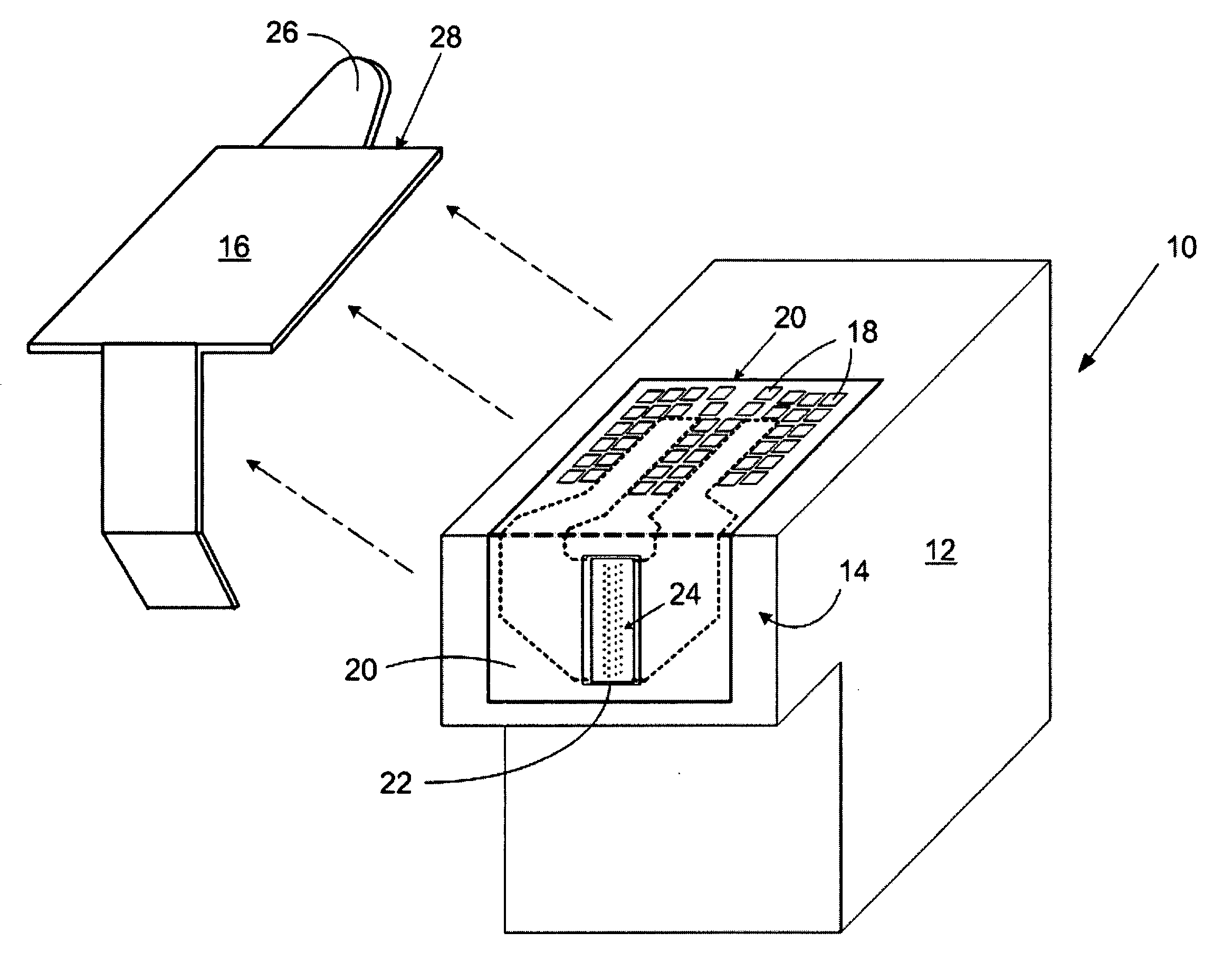
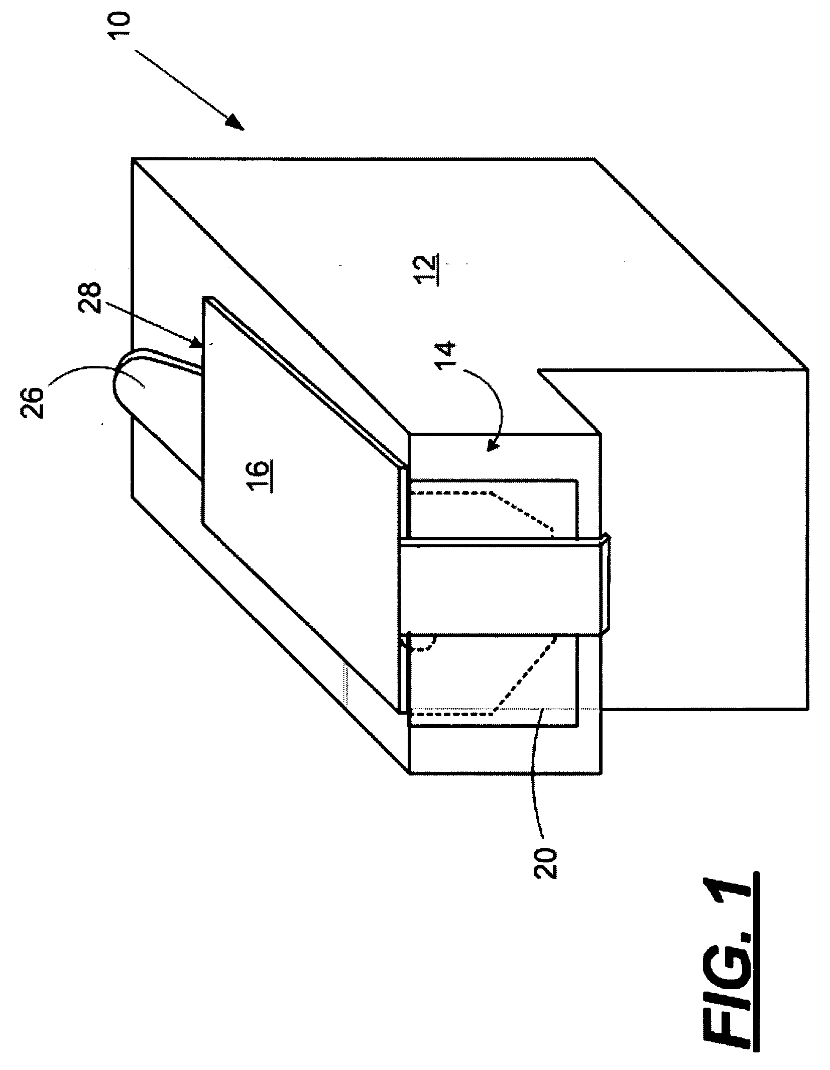
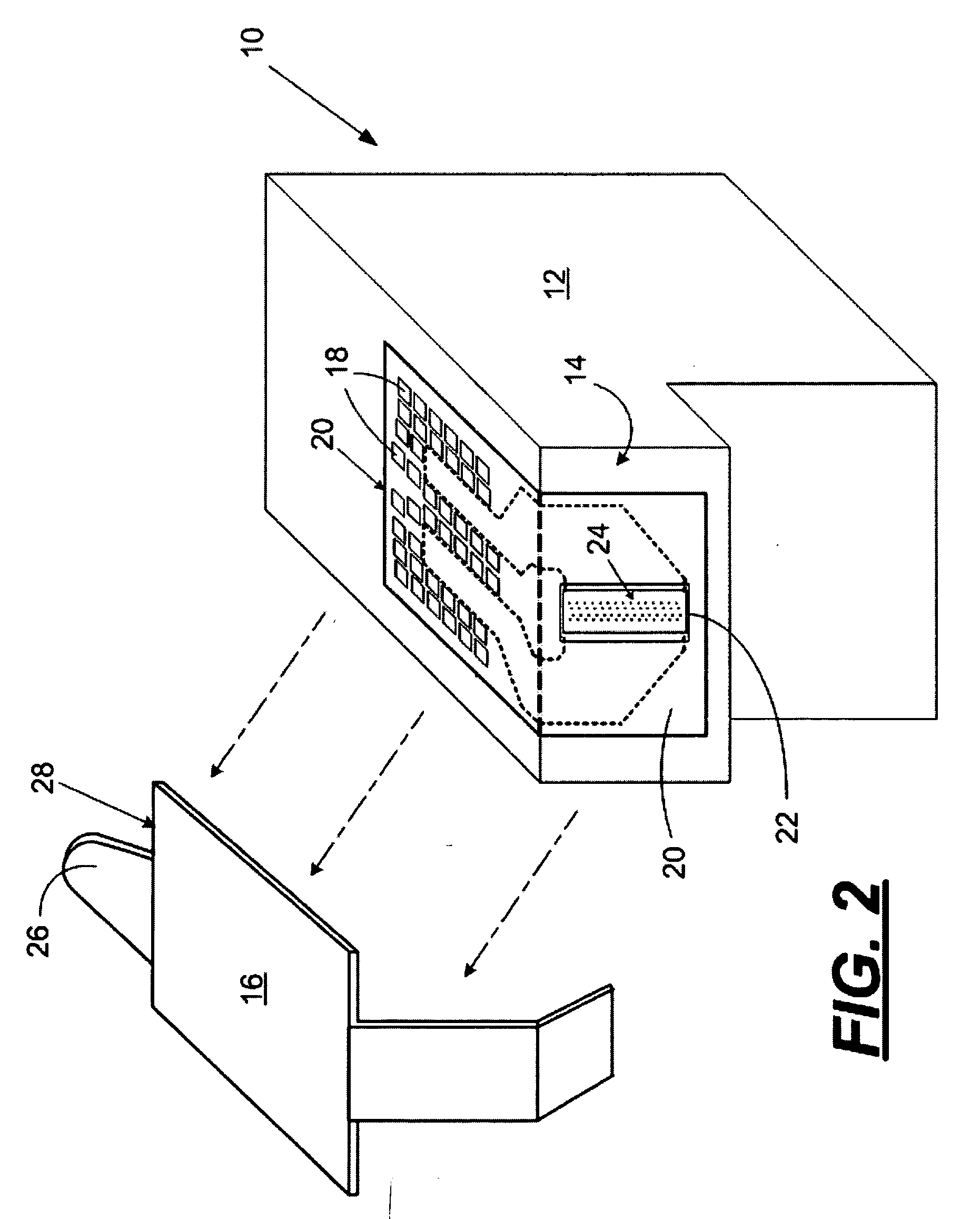
[0019] With reference to FIGS. 1 and 2 there are shown in perspective views, a fluid cartridge 10 including a fluid reservoir body 12 and a micro-fluid ejection head 14. A sealing and protective tape 16 is applied to the fluid cartridge body 12 to cover electrical contacts 18 (FIG. 2) on a flexible circuit 20 and a nozzle plate 22 (FIG. 2) for the ejection head 14.

[0020] The protective tape 16 is used to protect the contacts 18 on the flexible circuit 20 from contamination and damage, and to seal nozzle holes 24 in the nozzle plate 22 so that the fluid in the cartridge 10 does not leak out or dry and plug the nozzle holes 24. Before the cartridge 10 is installed in a device, such as a printer, for causing fluid to be ejected through the nozzle holes 24, the tape 16 is pealed away from the cartridge body 12 by grasping a tab 26 on one end 28 of the tape 16 and pulling the tape 16 away from the cartridge body 12 as shown schematically by FIG. 2.

[0021] As shown in more detail in FIG....


PUM


Abstract

An orifice plate sealing tape for an orifice plate of a micro-fluid ejection device and methods for sealing an orifice plate with the sealing tape. The sealing tape includes a flexible polymeric backing film and a radiation cured adhesive applied to a surface of the orifice plate. The adhesive is cured in a pattern sufficient to seal adjacent to nozzle holes in the orifice plate and to enhance removal of the backing film and adhesive from the orifice plate prior to use of the micro-fluid ejection device. Upon removal of the sealing tape, a minimum of residue is left on the nozzle plate surface adjacent to and/or in the nozzle holes.

Description

FIELD OF THE DISCLOSURE [0001] The disclosure relates to micro-fluid ejection heads and in particular to protection devices for orifice plates of the ejection heads. BACKGROUND AND SUMMARY [0002] Micro-fluid ejection devices have continued to find application in a variety of fields including, but not limited to, ink jet printing, micro-fluid heat transfer, micro-biological preparations, pharmaceutical delivery and the like. As higher quality ejection devices are produced, it becomes increasingly important to protect the orifice plates on the ejection heads during handling, storage, and shipping of the devices so that contamination of fluids or plugging of orifices does not occur. Conventionally, cover tapes are applied to the orifice plates and are removed prior to use of the devices. The cover tapes should be sufficient to adequately seal the orifices to prevent evaporation and intermixing of fluids and should be constructed of materials that are resistant to and do not contaminate...

Claims


Application Information

Patent Timeline
Patent Type & Authority Applications(United States)
IPC IPC(8): B41J2/165
CPCB41J2/17536
Inventor BERTELSEN, CRAIG M.MOORE, RICHARD MICHAELROSA, DELL T.SANGALLI, JEFFERY L.STOKESBARY, JERRY E.WALDECK, MELISSA M.
Owner FUNAI ELECTRIC CO LTD
Why Eureka
Try Eureka