Inkjet printhead heater elements with thin or non-existent coatings

a technology of resistive heaters and printheads, applied in printing, other printing apparatus, inking apparatus, etc., can solve the problems of difficult integration of sensors, difficult operation of resistive heaters in extremely harsh environments, and increase the complexity of fabrication processes, so as to reduce or eliminate thermal insulation, improve printhead efficiency, and reduce the effect of energy consumption

Active Publication Date: 2006-10-05
SILVERBROOK RES TY
View PDF7 Cites 11 Cited by
  • Summary
  • Abstract
  • Description
  • Claims
  • Application Information

AI Technical Summary

Benefits of technology

[0023] Removing most or all of the protective coatings from the heater reduces or eliminates the thermal insulation between the heater and the ink. The energy required to heat any protective coating scales directly with the coating thickness. Diffusive loss of energy into the ink and supporting underlayer (if any) prior to bubble nucleation is also significantly reduced by thinning or removing any protective coatings. Nucleating a bubble in the ink chamber requires a much shorter pulse of less energy thereby improving printhead efficiency.

Problems solved by technology

However, the microscopic scale of the chambers and nozzles makes the incorporation of sensors difficult and adds extra complexity to the fabrication process.
The resistive heaters operate in an extremely harsh environment.
Dissolved oxygen in the ink can attack the heater surface and oxidise the heater material.
In extreme circumstances, the heaters ‘burn out’ whereby complete oxidation of parts of the heater breaks the heating circuit.
The heater can also be eroded by ‘cavitation’ caused by the severe hydraulic forces associated with the surface tension of a collapsing bubble.
Consequently, the heat absorbed by the protective layers limits the density of the nozzles on the printhead and the nozzle firing rate.
This in turn has an impact on the print resolution, the printhead size, the print speed and the manufacturing costs.
Attempts to increase nozzle density and firing rate are hindered by limitations on thermal conduction out of the printhead integrated circuit (chip), which is currently the primary cooling mechanism of printheads on the market.
Inkjet printheads can also suffer from nozzle clogging from dried ink.
The increase in viscosity will also decrease the momentum of ink forced through the nozzle and increase the critical wavelength for the Rayleigh Taylor instability governing drop break-off, decreasing the likelihood of drop break-off.
If the nozzle is left idle for too long, the nozzle is unable to eject the liquid in the chamber.

Method used


Image

  • Inkjet printhead heater elements with thin or non-existent coatings
  • Inkjet printhead heater elements with thin or non-existent coatings
  • Inkjet printhead heater elements with thin or non-existent coatings

Examples


Embodiment Construction

[0233] In the description than follows, corresponding reference numerals, or corresponding prefixes of reference numerals (i.e. the parts of the reference numerals appearing before a point mark) which are used in different figures relate to corresponding parts. Where there are corresponding prefixes and differing suffixes to the reference numerals, these indicate different specific embodiments of corresponding parts.

Overview of the Invention and General Discussion of Operation

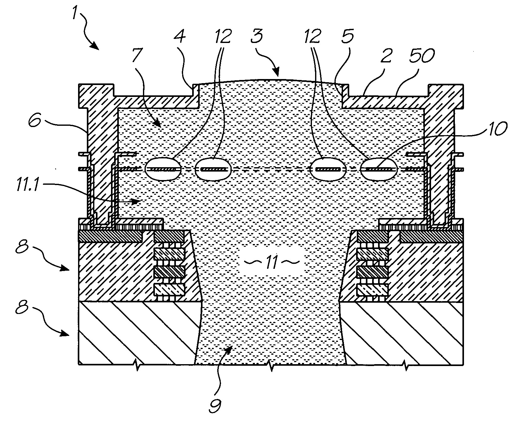
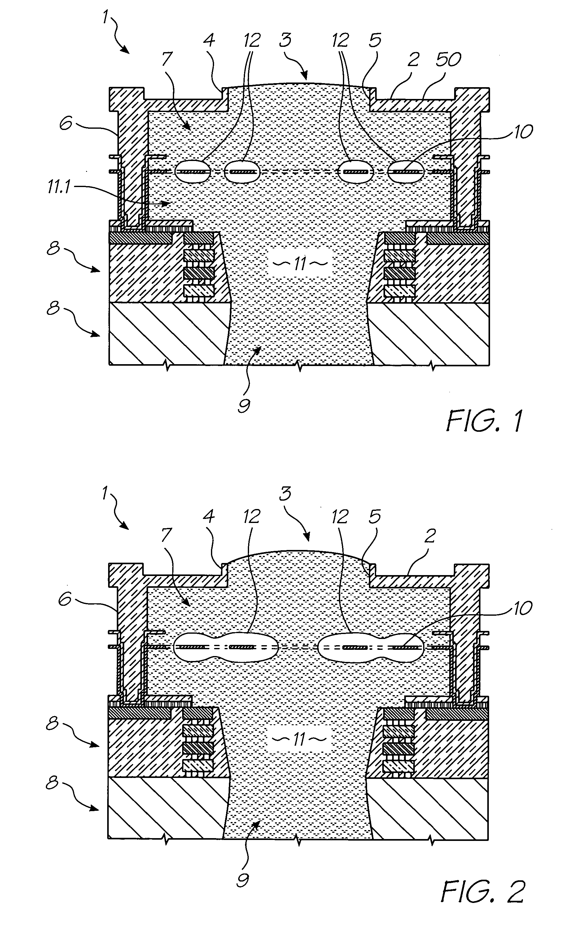
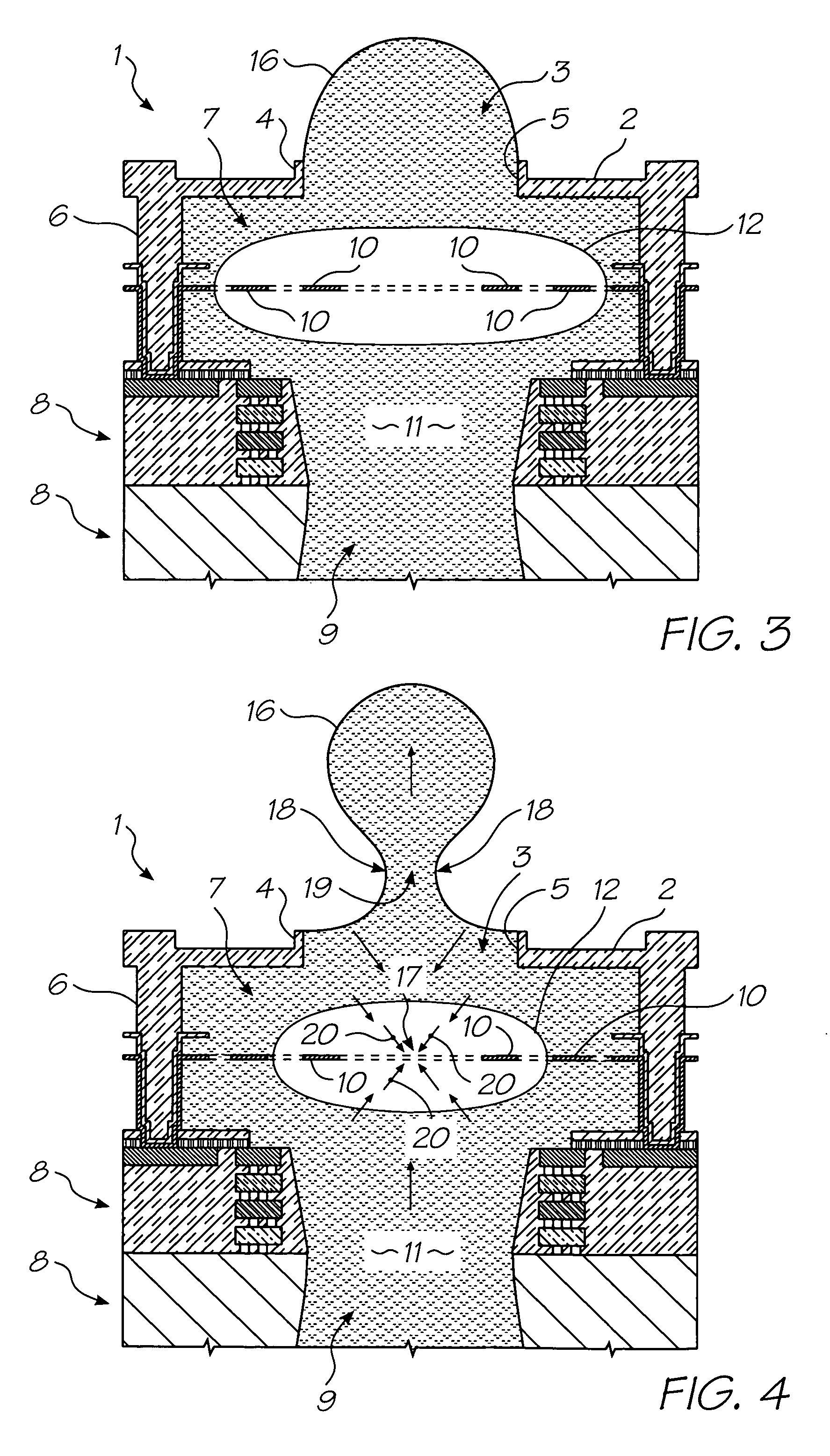
[0234] With reference to FIGS. 1 to 4, the unit cell 1 of a printhead according to an embodiment of the invention comprises a nozzle plate 2 with nozzles 3 therein, the nozzles having nozzle rims 4, and apertures 5 extending through the nozzle plate. The nozzle plate 2 is plasma etched from a silicon nitride structure which is deposited, by way of chemical vapor deposition (CVD), over a sacrificial material which is subsequently etched.

[0235] The printhead also includes, with respect to each nozzle 3, side ...


PUM


Abstract

A thermal inkjet printhead with a heater element disposed in each of the bubble forming chambers wherein, the heater element has a protective surface coating that is less than 0.1 μm thick while still being capable of ejecting more than 1 billion drops without failure. Removing most or all of the protective coatings from the heater reduces or eliminates the thermal insulation between the heater and the ink. Nucleating a bubble in the ink chamber requires a much shorter pulse of less energy thereby improving printhead efficiency.

Description

FIELD OF THE INVENTION [0001] The present invention relates to inkjet printers and in particular, inkjet printheads that generate vapor bubbles to eject droplets of ink. CO-PENDING APPLICATIONS [0002] The following applications have been filed by the Applicant simultaneously with the present application: MTC001USMTC004USMTC006USMTC007USMTC008USMTC010US[0003] The disclosures of these co-pending applications are incorporated herein by reference. The above applications have been identified by their filing docket number, which will be substituted with the corresponding application number, once assigned. CROSS REFERENCES TO RELATED APPLICATIONS [0004] The following patents or patent applications filed by the applicant or assignee of the present invention are hereby incorporated by cross-reference. 675090167509016476863678833611 / 00378611 / 00335411 / 00361611 / 00341811 / 00333411 / 00360011 / 00340411 / 00341911 / 00370011 / 00360111 / 00361811 / 00361511 / 00333711 / 00369811 / 00342011 / 00368211 / 003699CAA018US11...

Claims


Application Information

Patent Timeline
Patent Type & Authority Applications(United States)
IPC IPC(8): B41J2/05
CPCB41J2/1412B41J2/155B41J2/1601B41J2/1623B41J2/1628B41J2/1631B41J2202/20B41J2/1642B41J2/1645B41J2/1646B41J2002/1437B41J2002/14491B41J2/1639
Inventor SILVERBROOK, KIAMCAVOY, GREGORY JOHNNORTH, ANGUS JOHNMALLINSON, SAMUEL GEORGEAZIMI, MEHDI
Owner SILVERBROOK RES TY
Why Eureka
Try Eureka