Interposable heat sink for adjacent memory modules

Inactive Publication Date: 2006-10-05
IBM CORP
View PDF21 Cites 25 Cited by
  • Summary
  • Abstract
  • Description
  • Claims
  • Application Information

AI Technical Summary

Benefits of technology

[0010] When abutting opposing electronic components, a single heat sink de

Problems solved by technology

Further still, newer CPUs are tending to run hotter, and the memory modules are receiving preheated air from

Method used


Image

  • Interposable heat sink for adjacent memory modules
  • Interposable heat sink for adjacent memory modules
  • Interposable heat sink for adjacent memory modules

Examples


Embodiment Construction

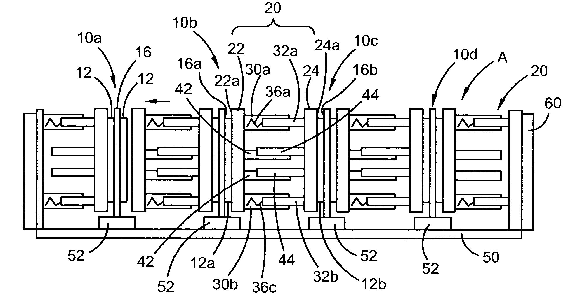
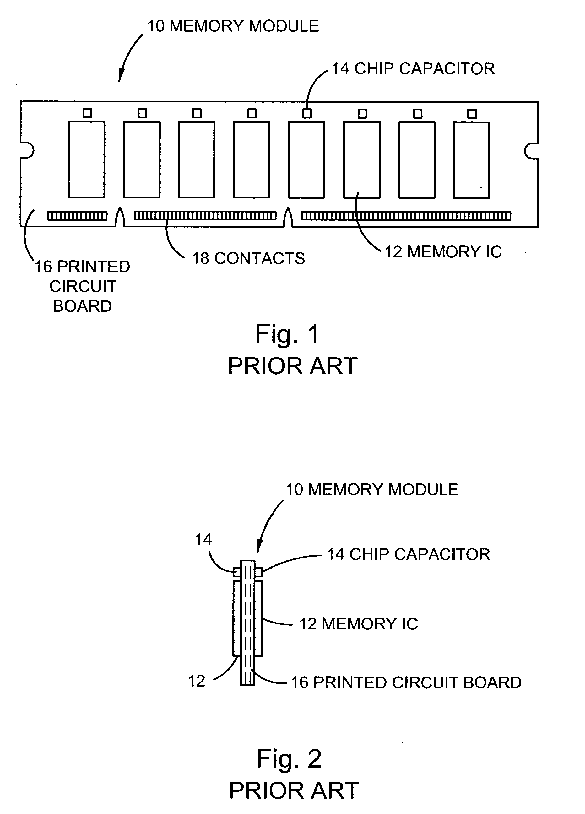
[0019] The present invention provides a heat sink device configured to dissipate heat from electronic components of a conventional memory module, such as a DIMM. Unlike a conventional heat sink device that is attached directly to a memory in an “on-the-module” design, the present invention provides heat sink devices configured to be interposed between adjacent memory modules in a “between-the-modules” design.

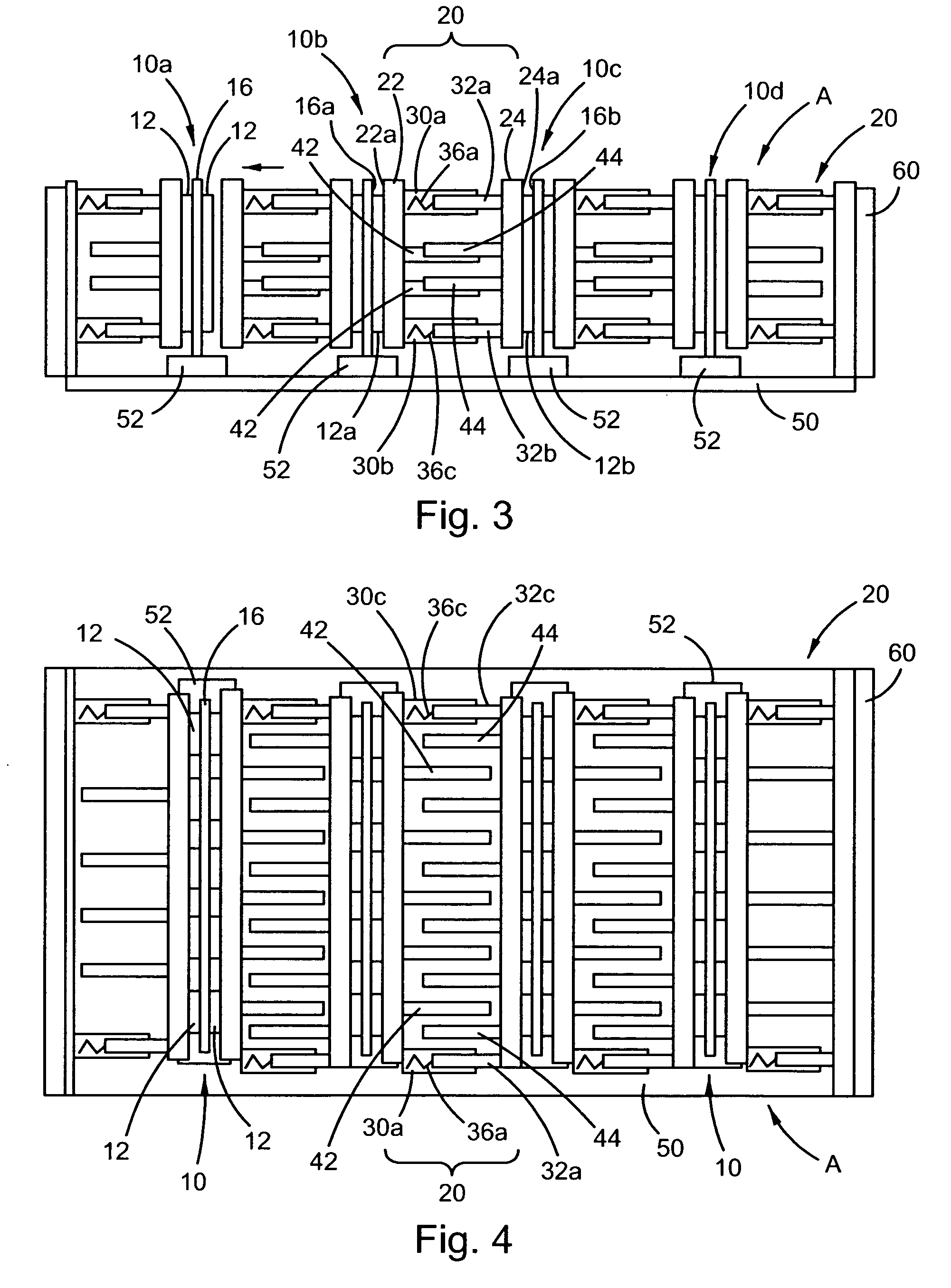
[0020] Referring now to FIGS. 3 and 4, heat sink devices 20 in accordance with one embodiment of the present invention are shown. It will be appreciated from FIGS. 3 and 4 that the heat sink devices 20 are configured to dissipate heat from conventional memory modules, such as DIMMs, while further, the inventive heat sink devices 20 can be installed and used without any need for any modification to the conventional memory module, and without the need for any tools. Further still, the heat sink devices are configured to be fitted to conventional memory modules after such modules ...


PUM


Abstract

A h9eat sink device for conventional memory modules, such as DIMMs, that is configured to be positioned between adjacent memory modules mounted in substantially parallel connectors on a printed circuit board. Each heat sink device includes thermally conductive first and second members configured to thermally couple with electronic components of a conventional memory module. The first and second members may be resiliently biased away from one another so that the resilient bias causes the members to abut respective electronic components when placed between adjacent memory modules. A separate wedge, or a lever-mounted wedge, may be provided for insertion between the members to urge them away from one another and into abutting relationship with electronic components on facing surfaces of the adjacent memory modules. When abutting opposing electronic components, a single heat sink device facilitates heat dissipation from both of the adjacent memory modules.

Description

FIELD OF THE INVENTION [0001] The present invention relates generally to a heat sink device configured to dissipate heat from electronic components of a conventional memory module, such as a SIMM or DIMM. DISCUSSION OF RELATED ART [0002] Conventional memory modules include multiple individual memory chips arranged on a printed circuit board that is configured to mate with a conventional connector of a motherboard of a PC, etc. Such conventional memory modules conform to industry standards of size, configuration etc. Exemplary memory modules include SIMMs and DIMMs. [0003] Recent increases in the integration density of memory integrated circuits on memory modules, and the development of newer memory ICs, such as DDR2 ICs, have resulted in memory modules that run “hotter.” Further, many vendors of conventional memory modules have lowered the DIMM junction temperature specifications while power requirements have increased. Further still, newer CPUs are tending to run hotter, and the me...

Claims


Application Information

Patent Timeline
IPC IPC(8): H05K7/20
CPCG06F1/184G06F1/185G06F1/186G06F1/20H01L2924/0002H01L23/367H01L2924/00
Inventor FOSTER, JIMMY G. SR.JUNE, MICHAEL S.KAMATH, VINODLOEBACH, BETH F.MAKLEY, ALBERT V.MATTESON, JASON A.
Owner IBM CORP
Why Eureka
Try Eureka