
Multi-channel adaptive speech signal processing system with noise reduction

a speech signal and adaptive technology, applied in the field of signal processing systems, can solve the problems of poor signal-to-noise ratio (snr), reducing speech recognition accuracy, masking, distortion, etc., and achieve the effects of improving downstream processing system performance, improving speech signal clarity and intelligibility, and enhancing communication

Active Publication Date: 2006-10-05
HARMAN BECKER AUTOMOTIVE SYST WAVEMAKERS
View PDF3 Cites 148 Cited by
  • Summary
  • Abstract
  • Description
  • Claims
  • Application Information

AI Technical Summary

Benefits of technology

[0009] This invention provides improved speech signal clarity and intelligibility. The improved speech signal enhances communication and improves downstream processing system performance across a wide range of applications, including speech detection and recognition. The improved speech signal results from substantially reducing noise, while retaining desired signal components.

Problems solved by technology

Speech signal processing systems often operate in noisy background environments.
Noisy background environments result in poor signal-to-noise ratio (SNR), masking, distortion, corruption of signals, and other detrimental effects on signals.
As a result, noisy background environments reduce the intelligibility and clarity of speech signals and reduce speech recognition accuracy.
Reliance on a fixed beamformer renders such systems susceptible to potentially wide variations in energy levels at each microphone in the array and the differences in SNR among the microphone signals.
Under such conditions, the fixed beamformer may actually reduce performance of the noise reduction signal processing system.
In particular, microphone signals with low SNR may contribute excessive noise to the beamformed output signal.
Thus, past GSC implementations did not provide a consistently reliable mechanism for reducing noise, and do not provide speech command or communication systems with a consistently noise free signal.

Method used


Image

  • Multi-channel adaptive speech signal processing system with noise reduction
  • Multi-channel adaptive speech signal processing system with noise reduction
  • Multi-channel adaptive speech signal processing system with noise reduction

Examples


Embodiment Construction

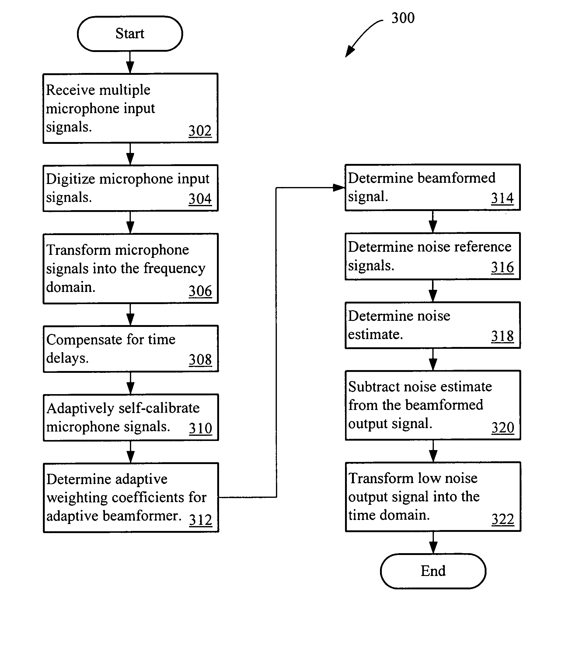
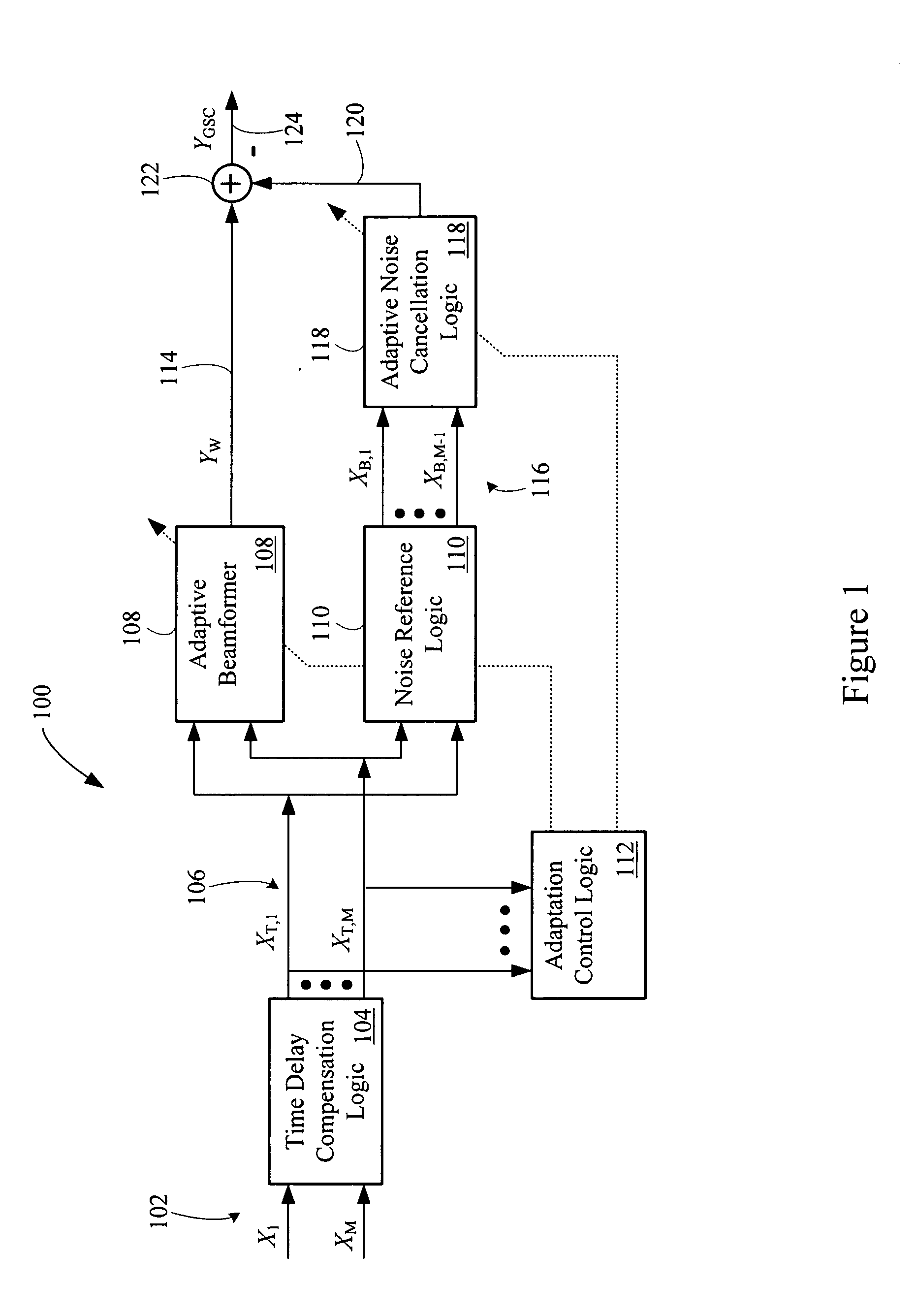
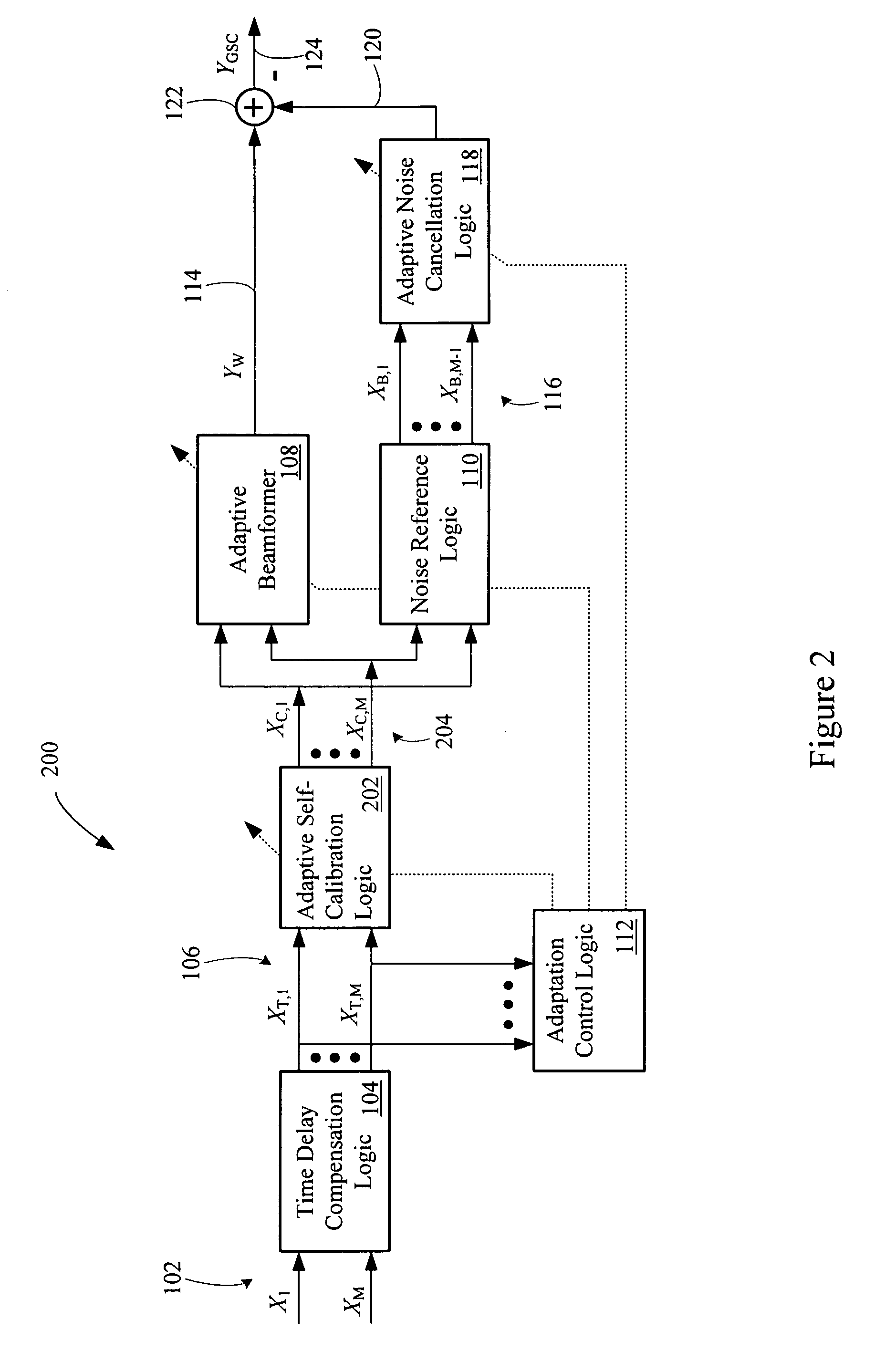
[0022]FIG. 1 shows a multi-channel adaptive speech processing system 100. The processing system 100 reduces noise originally present in one or more input signals. A low noise output signal results.

[0023] The processing system 100 includes microphone signal inputs 102. The microphone signal inputs 102 communicate microphone signals X1 to XM to time delay compensation logic 104. The microphone signals may be provided to the processing system 100 in the frequency domain and in sub-bands, denoted as X1(n,k) to XM(n,k), where the index ‘M’ denotes the number of microphones, ‘n’ is a frequency bin index, and ‘k’ is a time index. However, the processing system 100 may instead process the microphone signals in the time domain, a combination of the time domain and frequency domain, or in the frequency domain.

[0024] The time delay compensation logic 104 generates time aligned microphone signals XT,1 to XT,M on time delay compensated microphone signal outputs 106. The time delay compensated ...


PUM


Abstract

An adaptive signal processing system eliminates noise from input signals while retaining desired signal content, such as speech. The resulting low noise output signal delivers improved clarity and intelligibility. The low noise output signal also improves the performance of subsequent signal processing systems, including speech recognition systems. An adaptive beamformer in the signal processing system consistently updates beamforming signal weights in response to changing microphone signal conditions. The adaptive weights emphasize the contribution of high energy microphone signals to the beamformed output signal. In addition, adaptive noise cancellation logic removes residual noise from the beamformed output signal based on a noise estimate derived from the microphone input signals.

Description

PRIORITY CLAIM [0001] This application claims the benefit of priority from European Patent Application No. 04022677. 1, filed Sep. 23, 2004, which is incorporated herein by reference. BACKGROUND OF THE INVENTION [0002] 1. Technical Field. [0003] This invention relates to signal processing systems. In particular, this invention relates to multi-channel speech signal processing using adaptive beamforming. [0004] 2. Related Art. [0005] Speech signal processing systems often operate in noisy background environments. For example, a hands-free voice command or communication system in an automobile may operate in a background environment which includes significant levels of wind or road noise, passenger noise, or noise from other sources. Noisy background environments result in poor signal-to-noise ratio (SNR), masking, distortion, corruption of signals, and other detrimental effects on signals. As a result, noisy background environments reduce the intelligibility and clarity of speech sig...

Claims


Application Information

Patent Timeline
IPC IPC(8): A61F11/06G10K11/16H03B29/00G10L21/02G10L21/0208G10L21/0216
CPCG10L21/0208G10L21/0216H04R2430/25H04R3/005G10L2021/02166H04R29/006H04R2499/13G10L15/20G10L19/008
Inventor BUCK, MARKUSHAULICK, TIMHETHERINGTON, PHILLIP A.ZAKARAUSKAS, PIERRE
Owner HARMAN BECKER AUTOMOTIVE SYST WAVEMAKERS
Learn More