Hydrodynamic bearing device, spindle motor including the same, and recording and reproducing apparatus

a technology of bearing device and spindle motor, which is applied in the direction of sliding contact bearing, mechanical equipment, mechanical energy handling, etc., can solve the problems of increasing the height limit of the motor b>57/b>, miniaturizing and thinning the motor, etc., and achieves the effect of long spacing

Inactive Publication Date: 2006-10-05
PANASONIC CORP
View PDF5 Cites 59 Cited by
  • Summary
  • Abstract
  • Description
  • Claims
  • Application Information

AI Technical Summary

Benefits of technology

[0012] Therefore, the present invention aims to provide a hydrodynamic bearing device that can sufficiently secure the formable height of a radial bearing and that can ensure a sufficiently long spacing (span) between each radial bearings when a plurality of radial bearings are provided in the direction of the shaft center, and to provide a spindle motor including the hydrodynamic bearing device as well as a recording and reproducing apparatus mounted with the spindle motor.

Problems solved by technology

However, the height limit of the motor 57 is becoming more severe to miniaturize and thin the motor 57.

Method used


Image

  • Hydrodynamic bearing device, spindle motor including the same, and recording and reproducing apparatus
  • Hydrodynamic bearing device, spindle motor including the same, and recording and reproducing apparatus
  • Hydrodynamic bearing device, spindle motor including the same, and recording and reproducing apparatus

Examples


first embodiment

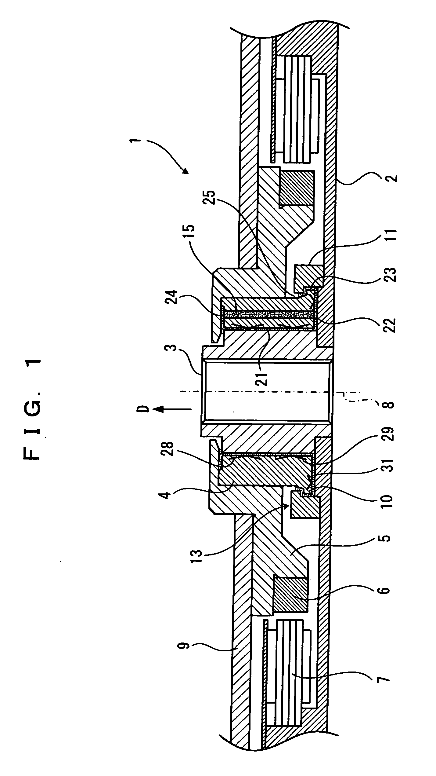
[0049] the present invention will now be explained based on FIG. 1 to FIG. 7.

[0050] As shown in FIG. 1, reference character 1 is a shaft fixed type spindle motor, where a base 2 (one example of shaft side member) is attached to and fixed to one end portion of the fixed shaft 3 (one example of shaft). A cylindrical sleeve 4 (one example of bearing body) is externally fitted to the fixed shaft 3 in a freely rotating manner. The lower end portion (one end portion) of the sleeve 4 is facing the base 2. A hub 5 (one example of bearing body side member) for receiving the disc 9 is attached to the upper end portion (other end portion) of the sleeve 4. A magnet 6 is provided on the hub 5. The stator 7 facing the magnet 6 from the outer side in the radial direction is provided on the base 2.

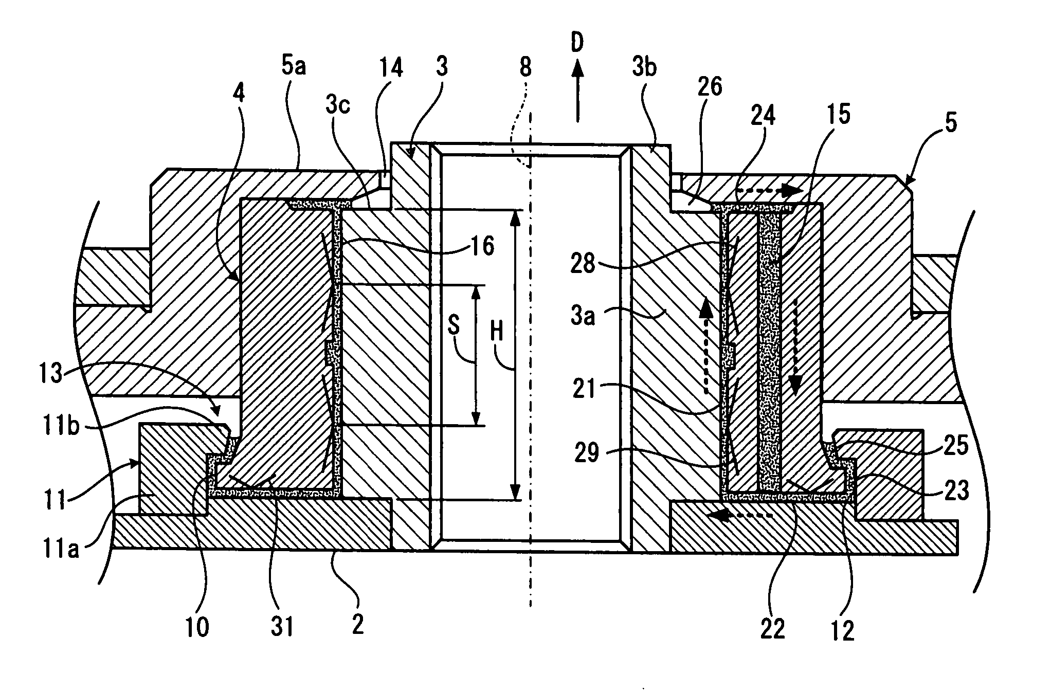
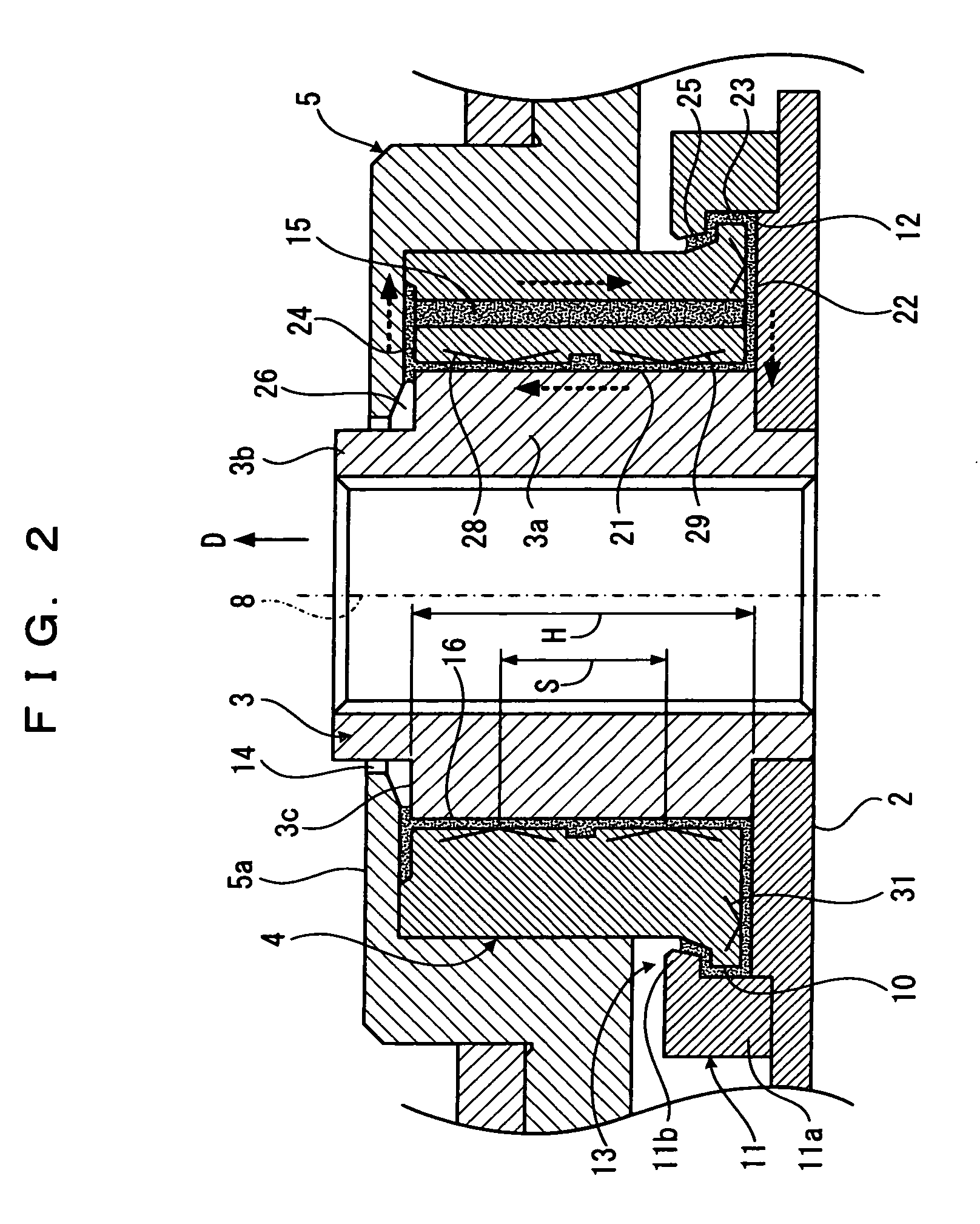
[0051] As shown in FIG. 2, the fixed shaft 3 includes a body shaft part 3a, a distal end shaft part 3b, and a stepped surface 3c. The distal end shaft part 3b is formed at the distal end of the body shaf...

second embodiment

[0086] That is, in the second embodiment, the radial dynamic pressure generating grooves 28a, 29a are formed on the inner peripheral surface of the sleeve 4, and the thrust dynamic pressure generating groove 31a is formed on the lower end face of the sleeve 4 and on the inner side in the radial direction than the communication hole 15.

third embodiment

[0087] In the third embodiment, the radial dynamic pressure generating grooves 28a, 29a are formed on the inner peripheral surface of the sleeve 4, and the thrust dynamic pressure generating groove 31a is formed on the lower end face of the sleeve 4 and on both the outer side and the inner side in the radial direction than the communication hole 15.


PUM


Abstract

A cylindrical sleeve is rotatably fitted over a fixed shaft erected on a base, the sleeve including an outer collar part at an outer periphery of the lower end portion thereof, a slip-out preventing member for preventing the slip-out from the fixed shaft while allowing the sleeve to rotate is provided on the base, the slip-out preventing member including an inner collar part that engages with the outer collar part in the slip-out direction. A hub is provided on the upper end portion of the sleeve, a pair of upper and lower radial bearings formed with a dynamic pressure generating groove are provided on the inner peripheral surface of the sleeve, and a thrust bearing formed with a dynamic pressure generating groove is provided at the lower end face of the sleeve.

Description

BACKGROUND OF THE INVENTION [0001] 1. Field of the Invention [0002] The present invention relates to a hydrodynamic bearing device used in a spindle motor such as a small HDD (Hard Disc Drive) motor of, for example, not more than one inch, a spindle motor including the hydrodynamic-bearing device, and a recording and reproducing apparatus mounted with the spindle motor. [0003] 2. Description of the Related Art [0004] In recent years, with entry of HDDs into AV (Audio Visual) products and home electrical products, the spindle motors are required to be compact, thin, highly accurate and have long life spans. In FIG. 10 showing a configuration of the spindle motor 57, a sleeve 52 is provided on a base 51, a rotating shaft 53 is inserted into the sleeve 52, and a hub 54 for receiving a disc 65 is attached to a distal end of the rotating shaft 53, which hub 54 is provided with a magnet 55. A stator 56 wound with coil is provided facing the inner peripheral side of the magnet 55. [0005] T...

Claims


Application Information

Patent Timeline
Patent Type & Authority Applications(United States)
IPC IPC(8): F16C32/06
CPCF16C17/107F16C33/745F16C33/1085F16C2370/12H02K7/086
Inventor UENOSONO, KAORU
Owner PANASONIC CORP
Why Eureka
Try Eureka