

Carriage-utilizing conveying equipment
a technology of conveying equipment and conveying shafts, applied in mechanical conveyors, lifting devices, railway components, etc., can solve the problems of time-consuming and costly maintenance and inspection, abnormal noise generation, etc., and achieve the effect of simple configuration, extremely inexpensive implementation, and low cos
- Summary
- Abstract
- Description
- Claims
- Application Information
AI Technical Summary
Benefits of technology
Problems solved by technology
Method used
Image

Examples
Embodiment Construction
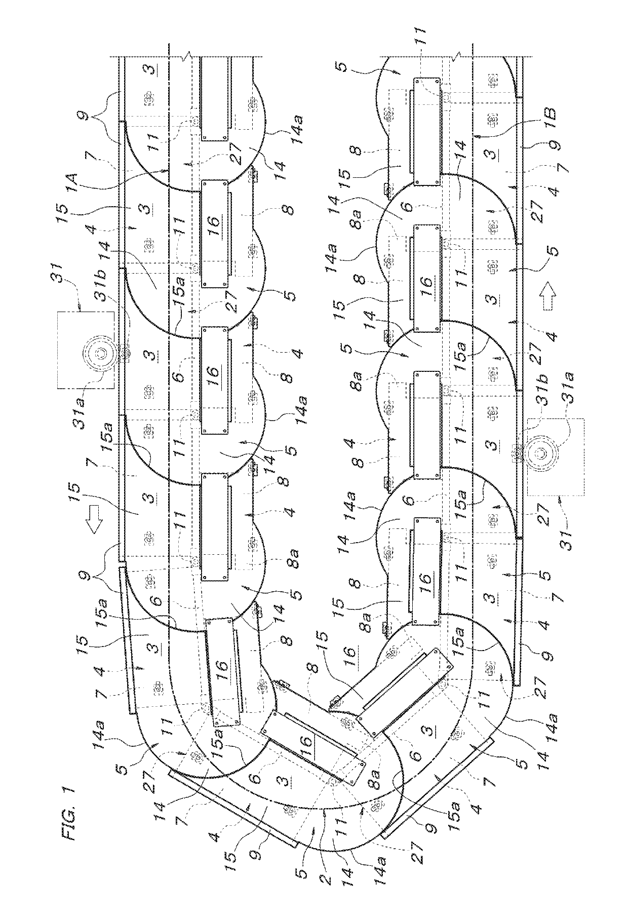
[0015]An embodiment of the present invention will be described below with reference to FIGS. 1 to 5B, and in this embodiment, the present invention is implemented as conveying equipment including workpiece-conveying carriages which travel on a circulation traveling path formed with two parallel reciprocating linear path sections and leftward-curved horizontal curved path sections that connect together the two reciprocating linear path sections at both ends thereof. FIG. 1 shows a state of respective carriages 3 which travel in a traveling path region extended from an outward linear path section 1A through the horizontal curved path section 2 that makes a U-turn of 180 degrees to a return linear path section 1B.
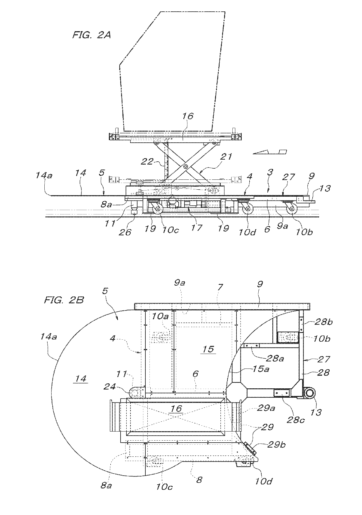
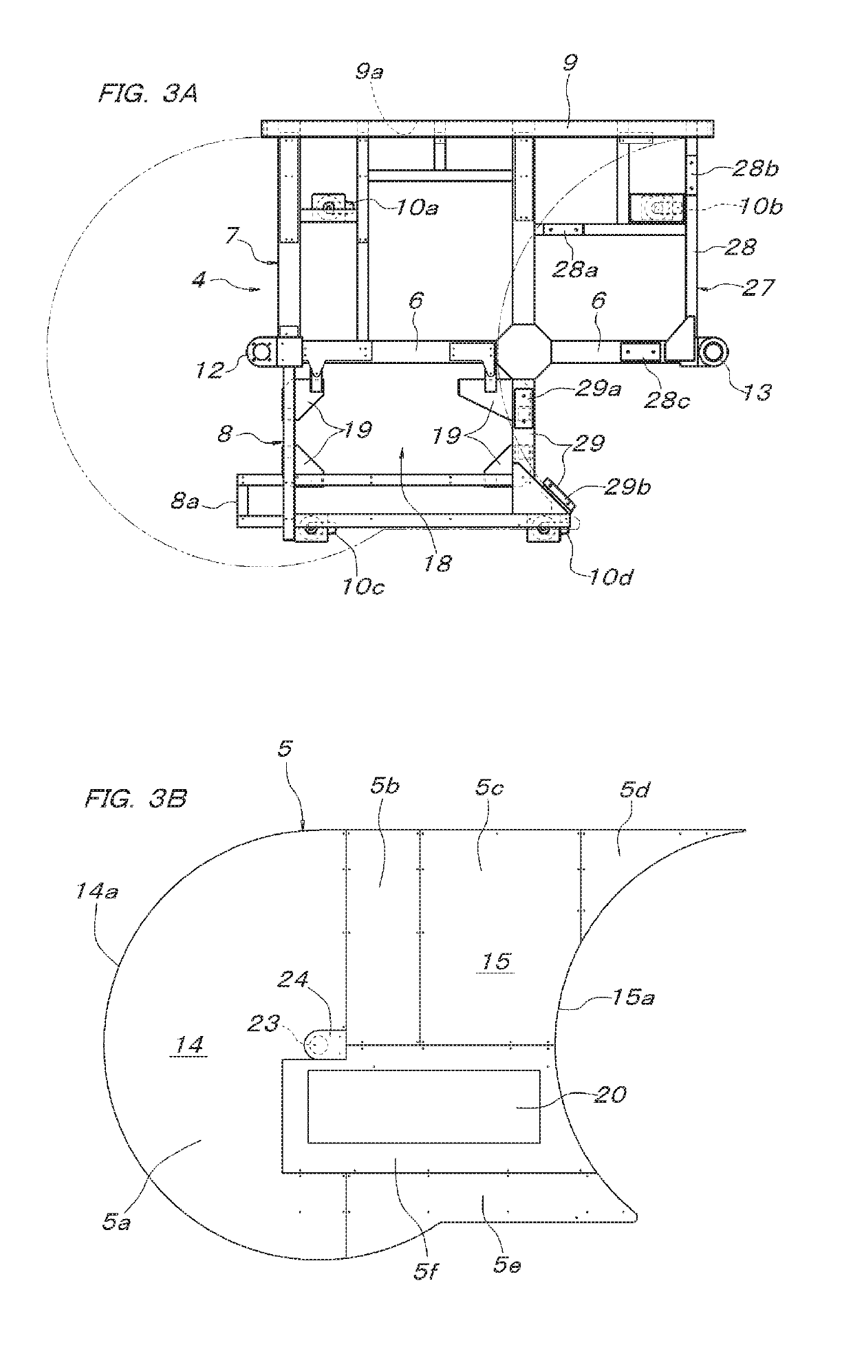
[0016]The structure of the carriage 3 will first be described. The carriage 3 is formed with a frame portion 4 and a floor board portion 5 which is laid on the frame portion. The frame portion 4 is formed with a rod-shaped center member 6 which is formed with a rectangular ste...
PUM
 Abstract
Description
Claims
Application Information