
System for predicting exterior ballistics

a technology of exterior ballistics and system, applied in the field of firearms, can solve the problems of no formal procedure to ensure agreement between, no computation becomes considerably more complicated, and the cost of doppler systems is high. achieve the effect of longer spacing

Active Publication Date: 2016-09-08
OEHLER III KENNETH L
View PDF3 Cites 2 Cited by
  • Summary
  • Abstract
  • Description
  • Claims
  • Application Information

AI Technical Summary

Benefits of technology

The present invention is an improved system for predicting exterior ballistics. It overcomes the disadvantages of previous systems by using two bullet detecting arrays and a common time signal facility to generate time signals and determine the velocity and time of passage of a bullet. The distance between the detectors is used to determine the initial velocity. Other detecting arrays at longer spacing along the trajectory are also used to record the time at which the bullet passes each array to get the flight time of the bullet. A data processing device is used to compute the ballistic coefficient that predicts the observed time of flight at the nearest distance. The present invention takes into account the cumulative effect of bullet drag over a distance approaching the maximum effective range of the bullet. The predicted time-of-flight is the same as observed experimentally. The invention has many advantageous features and provides an improved method for predicting exterior ballistics.

Problems solved by technology

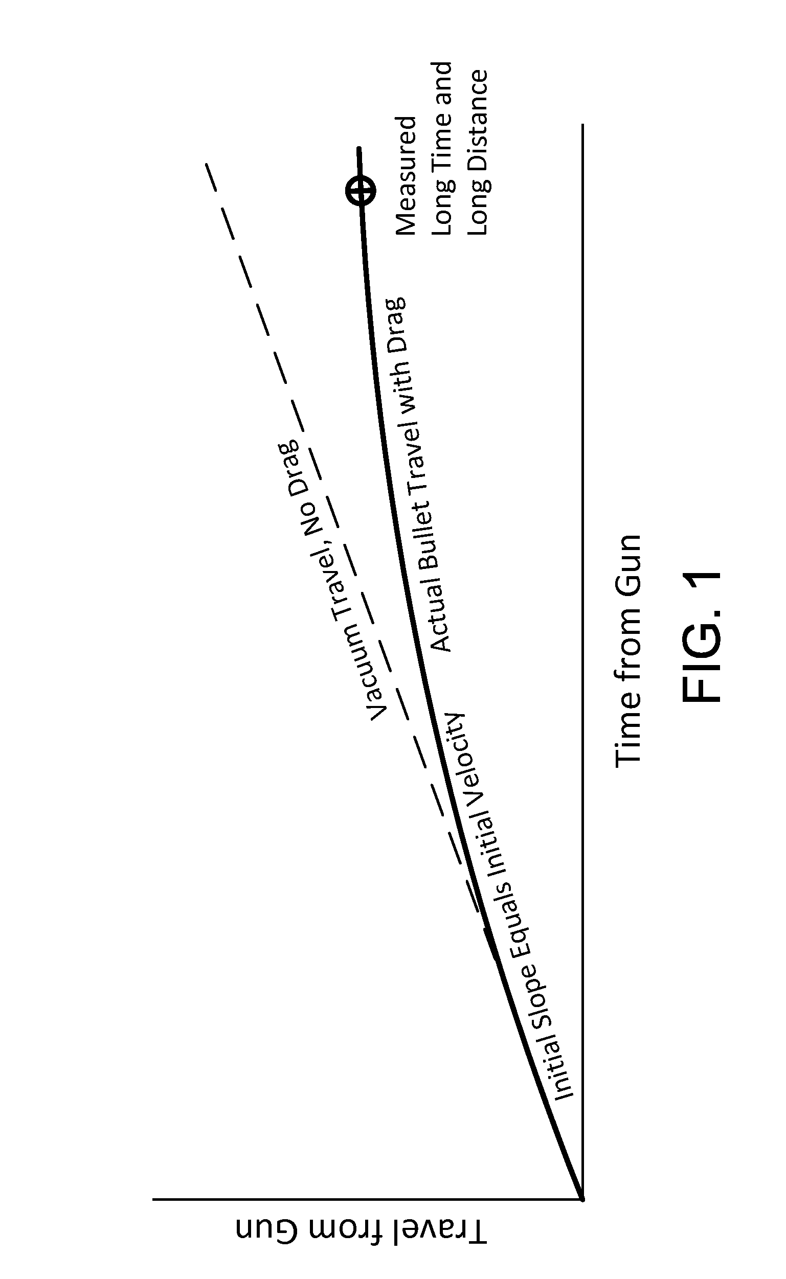
However, the computation becomes considerably more complicated when the slowing of the bullet caused by air resistance is considered.
There has been no formal procedure to assure agreement between predictions and measured results at intermediate ranges.
This point characterizes the cumulative long range performance of the bullet, but has historically been neglected because it is difficult to measure.
Second, the curve predicted from the assumed drag function and ballistic coefficient must pass through the measured long time and long distance point where the bullet impacts the target.
However, such Doppler systems are very expensive, they are not man-portable, and they require significantly more support.

Method used


Image

  • System for predicting exterior ballistics
  • System for predicting exterior ballistics
  • System for predicting exterior ballistics

Examples


Embodiment Construction

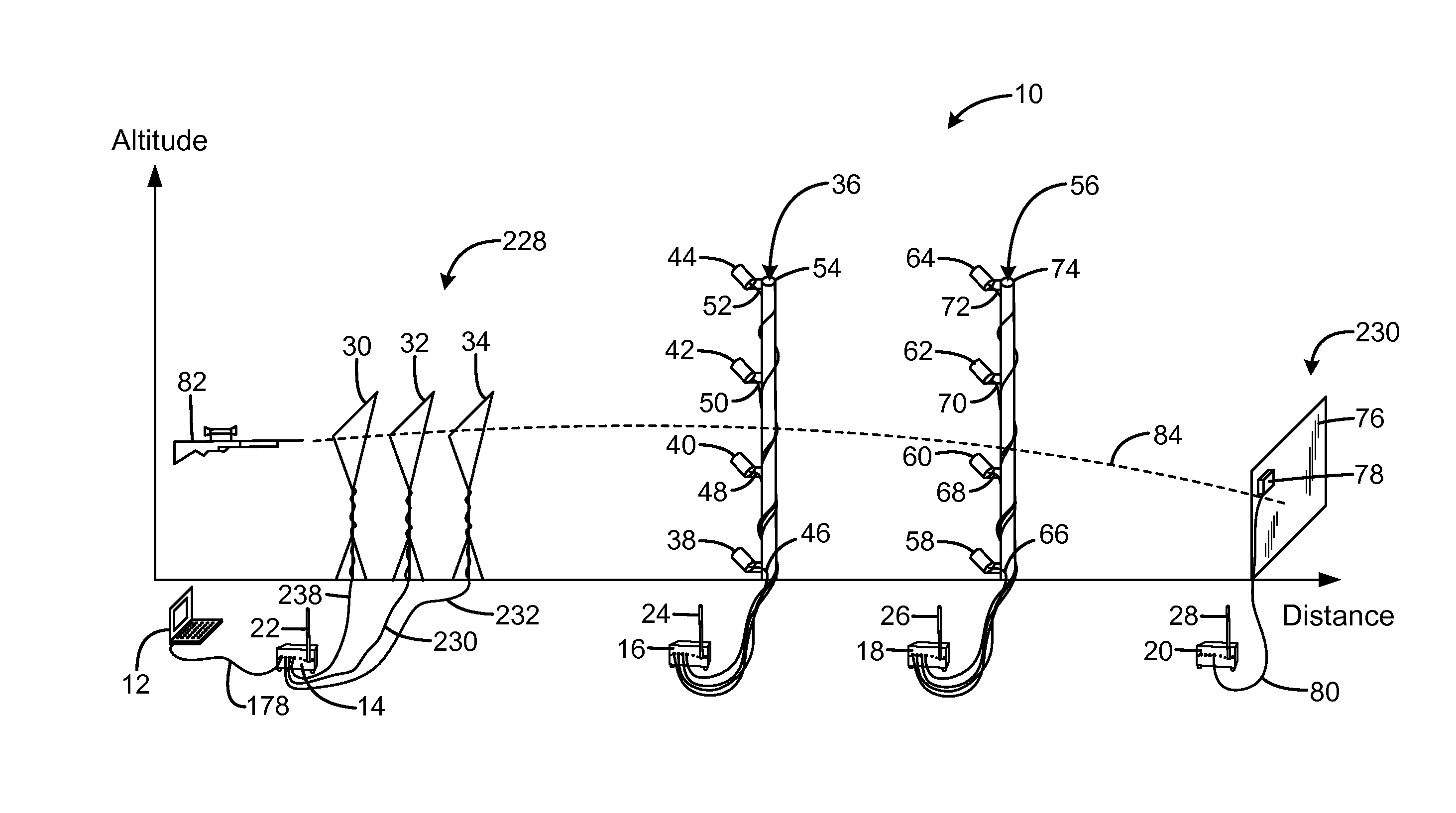
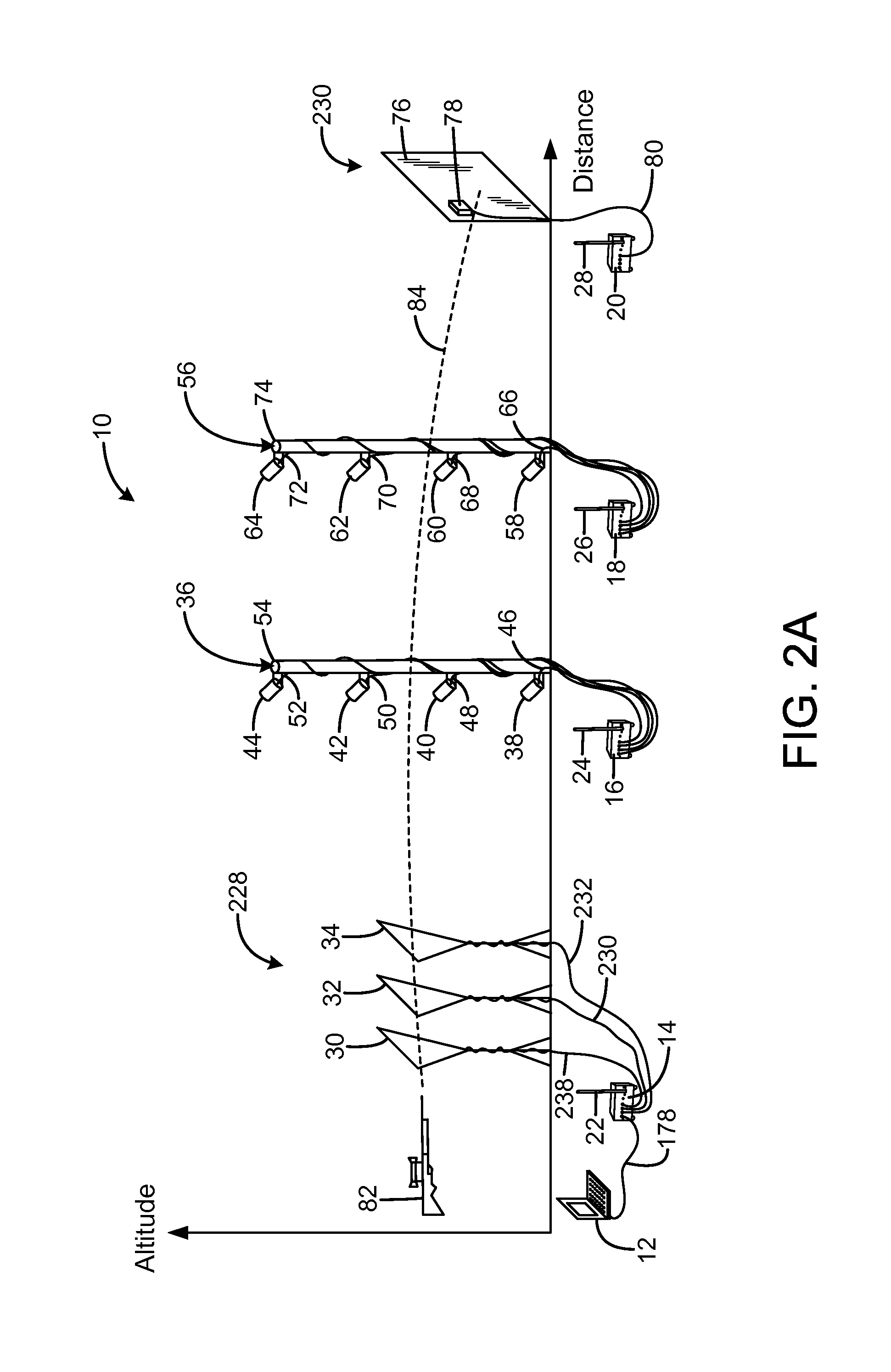
[0029]An embodiment of the system for predicting exterior ballistics of the present invention is shown and generally designated by the reference numeral 10.

[0030]FIGS. 2A & 2B illustrate the improved system for predicting exterior ballistics 10 of the present invention. More particularly, the system 10 addresses the three primary sources of bullet path prediction errors. The system measures the initial velocity V0 of the bullet from the gun 82 of interest using the muzzle velocity measurement unit 228. The system allows the assumption of a specific G(v) drag function approximately describing the bullet. Instead of requesting an input of the associated ballistic coefficient C, the system measures the initial velocity and time-of-flight to the known distance, and then computes the value of C required for the assumed G(v) to accurately predict the observed time-of-flight. This value of C can then be used with the assumed G(v) and the traditional predictive equations and procedures to a...


PUM


Abstract

A system for predicting exterior ballistics has first and second bullet detectors operable to detect the passage of a bullet, the first and second bullet detectors being spaced apart by a selected detector spacing distance, the first and second bullet detector each being connected to a common time signal facility that generates a time signal, the first bullet detector being operable to generate a first time of passage based on the time signal, the second bullet detector being operable to generate a second time of passage based on the time signal, the first bullet detector being operable to measure a first bullet velocity, a controller in communication with the first and second bullet detectors, and the controller operable based on the difference between the first time and the second time, and based on the first bullet velocity to calculate a ballistic characteristic for the bullet.

Description

CROSS-REFERENCE TO RELATED APPLICATION[0001]This application claims the benefit of U.S. Provisional Patent Application Number 62 / 128,873 filed on Mar. 5, 2015, entitled “SYSTEM FOR PREDICTING EXTERIOR BALLISTICS,” which is hereby incorporated by reference in its entirety for all that is taught and disclosed therein.FIELD OF THE INVENTION[0002]The present invention relates to firearms, and more particularly to a system that measures initial velocity and time of flight of a bullet to a known distance, calculates a ballistic coefficient for the bullet, and enhances the ability of traditional predictive equations and procedures to accurately predict bullet paths for other distances and conditions.BACKGROUND OF THE INVENTION[0003]For the last 150 years, riflemen have attempted to predict the paths of bullets fired over a long range. The discovery that the bullet path is parabolic when the effects of air resistance are ignored was derived much earlier by Galileo. However, the computation ...

Claims


Application Information

Patent Timeline
Patent Type & Authority Applications(United States)
IPC IPC(8): G01P3/64
CPCG01P3/64G01P3/665F41G5/00F41G5/08F41G11/00
Inventor OEHLER, KENNETH L.
Owner OEHLER III KENNETH L
Learn More