
Image destruct feature used with image receiving layers in secure documents

Active Publication Date: 2006-10-05
L 1 SECURE CREDENTIALING
View PDF32 Cites 6 Cited by
  • Summary
  • Abstract
  • Description
  • Claims
  • Application Information

AI Technical Summary

Benefits of technology

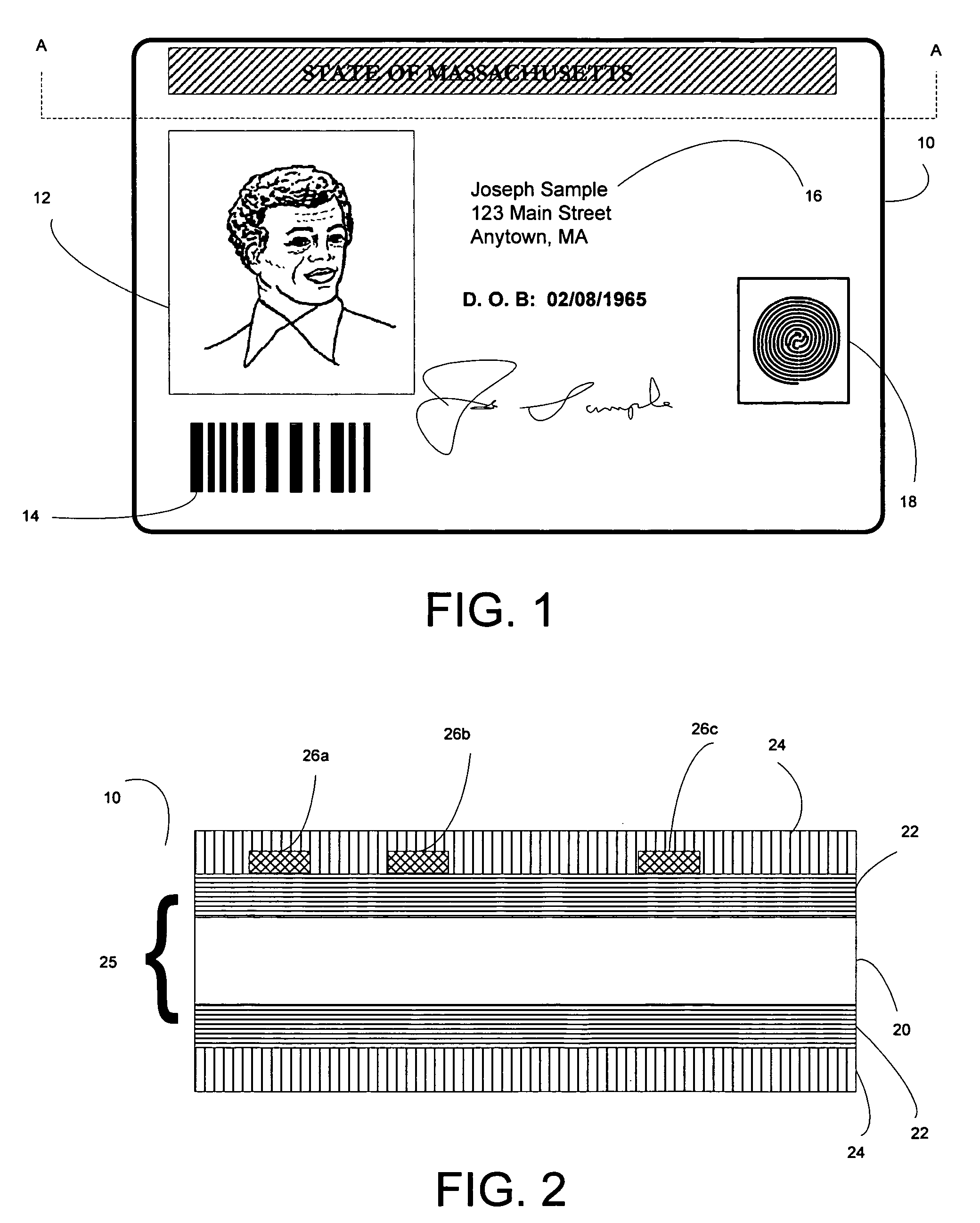
[0021] From the standpoint of security, an identification document should be difficult to tamper with and / or provide clear evidence of tampering. In particular, the various layers of the document, including the laminate, should be difficult to separate or intrude into without severely damaging the document and marring the information contained in it.
[0022] One way to protect the integrity of a secure document is to use overlaminate technology. Currently, PVC and composite cards used in secure ID documents rely on the overlaminate or a “transferred panel” (e.g., O-panel) to both physically protect the variable data printed on the card and to provide security for this data. In these card systems, the overlaminate is expected to fracture along a plane or tear when a counterfeiter attempts to remove it, resulting in an unusable card. Though this removal typically renders the overlaminate unusable, the remainder of the card is still usable in many cases. In some cases, both are re-usable. This allows the counterfeiter to alter or reuse the personalized card and, if needed, replace the overlaminate or panel with a substitute.

Problems solved by technology

From the standpoint of security, an identification document should be difficult to tamper with and / or provide clear evidence of tampering.
In particular, the various layers of the document, including the laminate, should be difficult to separate or intrude into without severely damaging the document and marring the information contained in it.
In these card systems, the overlaminate is expected to fracture along a plane or tear when a counterfeiter attempts to remove it, resulting in an unusable card.
Though this removal typically renders the overlaminate unusable, the remainder of the card is still usable in many cases.

Method used


Image

  • Image destruct feature used with image receiving layers in secure documents
  • Image destruct feature used with image receiving layers in secure documents
  • Image destruct feature used with image receiving layers in secure documents

Examples


example 1

[0062]

Components and Formulation:Solid %Solvent89.80%MEK(100%)PVC (Oxychem-155)  10%BYK-306 0.20%100.00% 

example 2

[0063]

Components and Formulation:Solid %Solvent86.30%MEKPVC (Oxychem-155)13.5%BYK-3060.20%

[0064] The following image receiving layer formulations include a copolymer, plasticizer, and antioxidant. This combination increases printing dye density and film stability.

example 3

[0065]

TotalDry SolidWet15%Solid %20.00%ComponentStk. %%%Wt. kgVYNS-3100%73%14.60%2.19Dioctyl phthalate100%23%4.60%0.69IRANOX 245100% 1%0.20%0.03TINUVIN 5050100% 3%0.60%0.09MEK100%12Total100% 15


PUM

PropertyMeasurementUnit
Fractionaaaaaaaaaa
Fractionaaaaaaaaaa
Fractionaaaaaaaaaa

Abstract

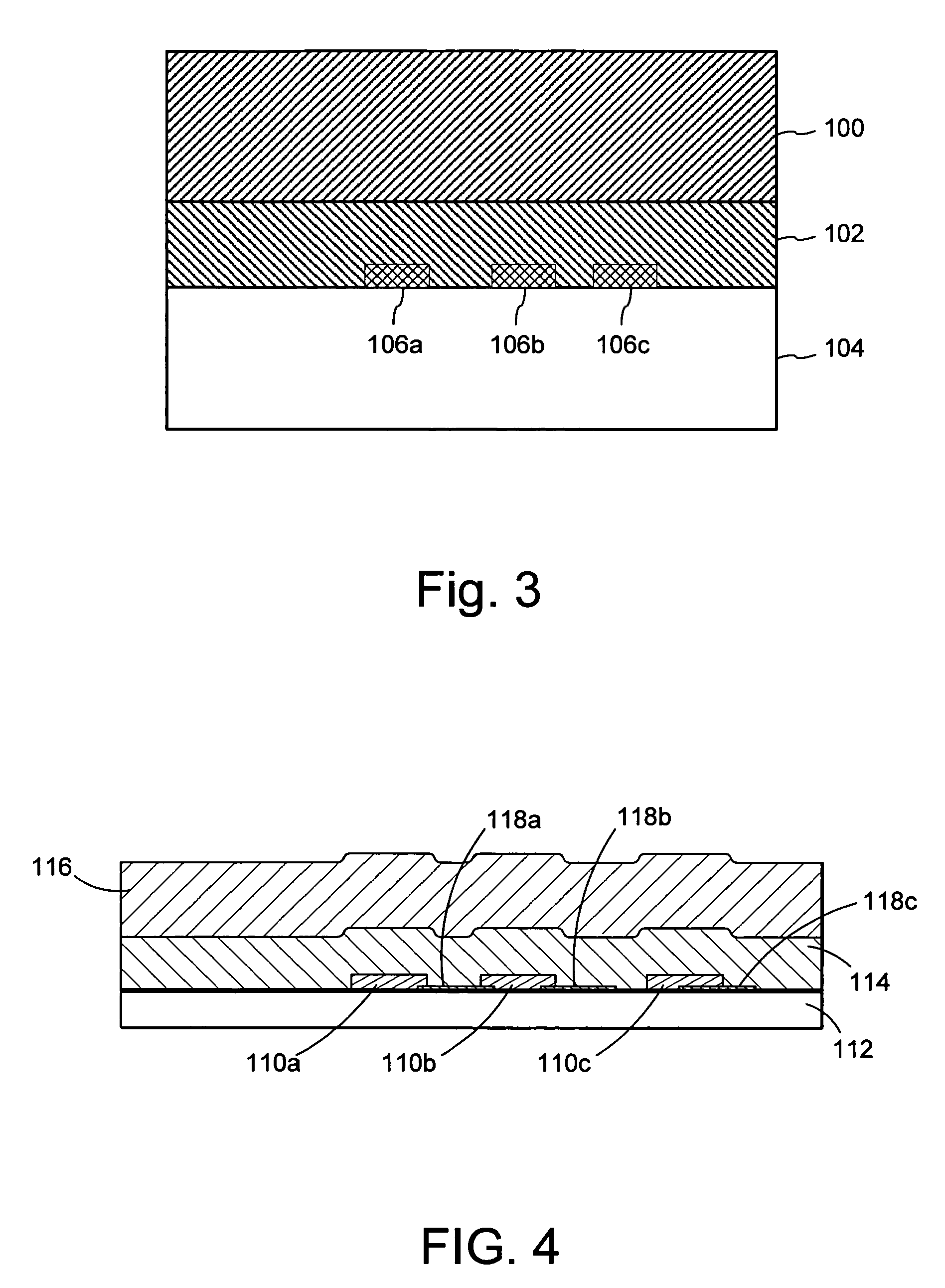
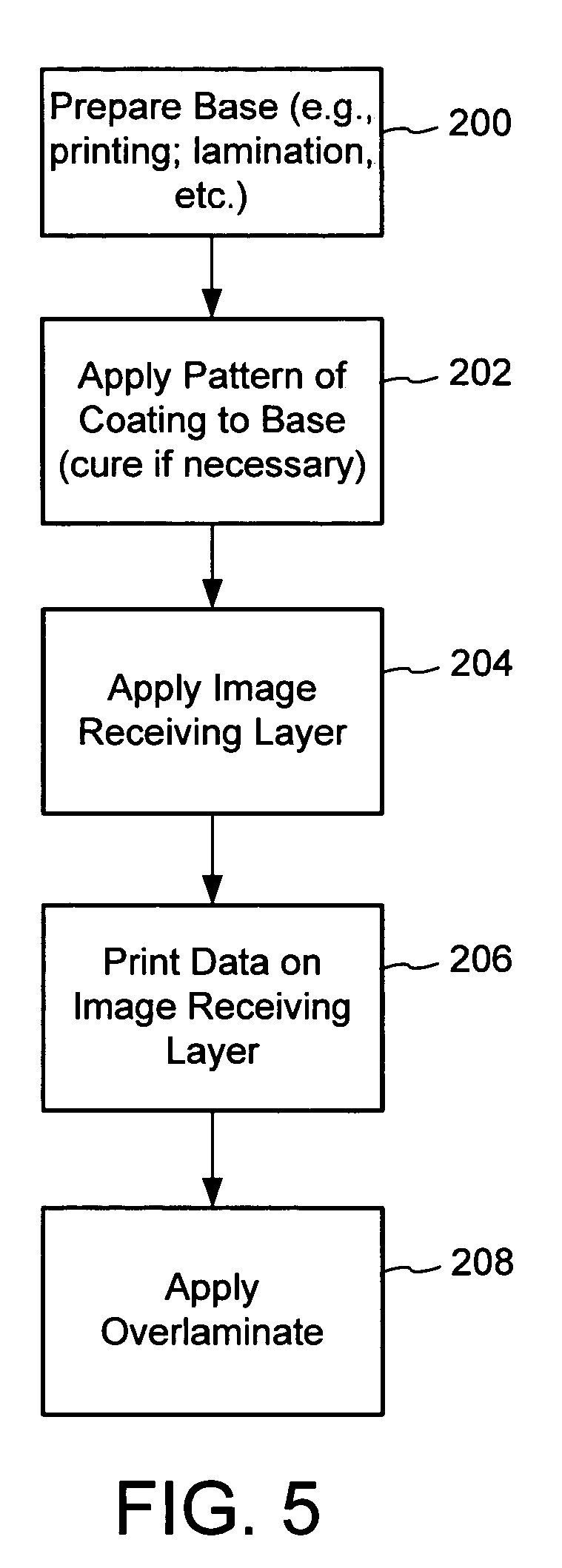
An image destruct material comprises a release layer positioned between an image receiving layer and a base layer. The adhesion between the release layer and the base layer is greater than adhesion between the release layer and the image receiving layer. The release layer material can be used in secure documents that have an image receiving layer, such as used for dye diffusion, mass transfer, ink jet, and xerographic printing. For example, particular implementations are designed for identification documents with a D2T2 image receiving layer. In these implementations, for example, the release layer is in the form of a patterned coating under the image receiving layer. After information is printed on the image receiving layer, an overlaminate is applied over it. Removal of the overlaminate destroys the printed image on the receiving layer because the relative adhesive properties of the image receiving layer, overlaminate and release layer cause the image to release with the overlaminate at the locations of the coating whereas the remainder of the image remains with the base layer.

Description

RELATED APPLICATION DATA [0001] This application is a continuation in part of U.S. application Ser. No. 11 / 096,229, filed Mar. 30, 2005, which is hereby incorporated by reference.TECHNICAL FIELD [0002] The invention relates to secure documents and specifically features of secure documents that make them tamper evident to deter or prevent document alteration and counterfeiting. BACKGROUND AND SUMMARY [0003] Identification documents (hereafter “ID documents”) play a critical role in today's society. One example of an ID document is an identification card (“ID card”). ID documents are used on a daily basis—to prove identity, to verify age, to access a secure area, to evidence driving privileges, to cash a check, and so on. Airplane passengers are required to show an ID document during check in, security screening and prior to boarding their flight. In addition, because we live in an ever-evolving cashless society, ID documents are used to make payments, access an automated teller machi...

Claims


Application Information

Patent Timeline
IPC IPC(8): B44C1/17
CPCB44C1/17Y10S428/916Y10T428/24802B42D25/455B42D25/46B42D25/00B42D25/47B42D25/23
Inventor BI, DAOSHENYEH, TUNG-FENGJONES, ROBERT L.LABREC, BRIAN C.
Owner L 1 SECURE CREDENTIALING
Learn More