Modular regenerative fuel cell system

Active Publication Date: 2006-10-05
SMITH & WESSON
View PDF30 Cites 54 Cited by
  • Summary
  • Abstract
  • Description
  • Claims
  • Application Information

AI Technical Summary

Benefits of technology

[0003] Regenerative fuel cell systems in which one or more electrochemical cells are utilized to both electrolyze water to produce hydrogen and oxygen, and to produce electricity by converting hydrogen and oxygen back into water, are known. These systems, which may be used with either renewable or non-renewable, grid connected or off-grid power sources, offer a mea

Problems solved by technology

Such an approach, however, may result in sub-optimal matching of

Method used


Image

  • Modular regenerative fuel cell system
  • Modular regenerative fuel cell system
  • Modular regenerative fuel cell system

Examples


Example

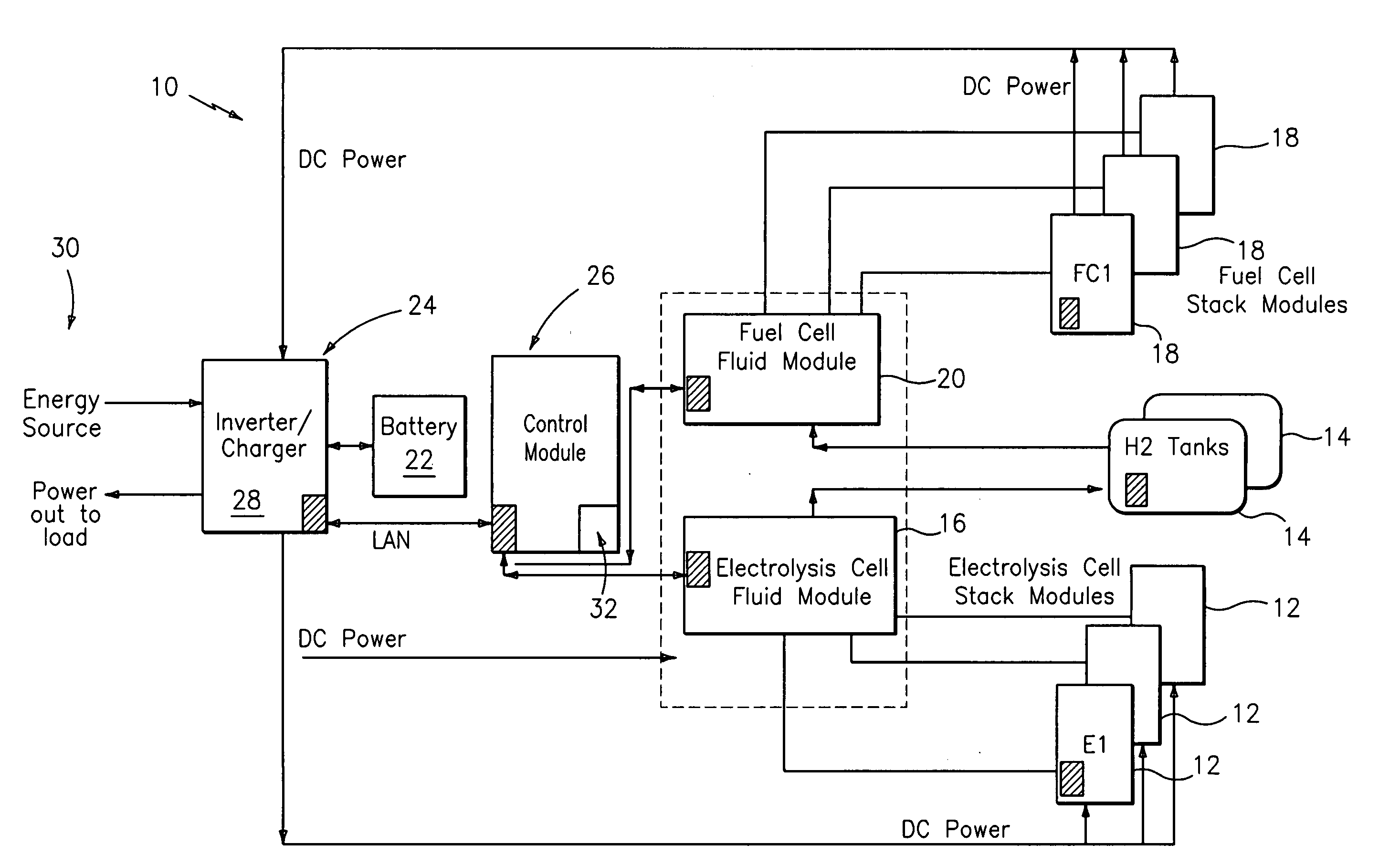
[0035] The preferred modular regenerative fuel cell system of the present invention offers a variety of modules, each directed toward a different system function. As such, the inventive system allows a user to specifically and effectively tailor the system to the demands of a particular application. If additional electrolysis capability and / or additional power are needed, only electrolysis cell stack modules and / or fuel cell stack modules are added to the system. The use of unnecessary or duplicative support equipment is avoided rendering the system more cost effective and efficient. Moreover, the inventive system offers a number of packaging options including a wall mounting packaging option in addition to floor and rack mounting options.

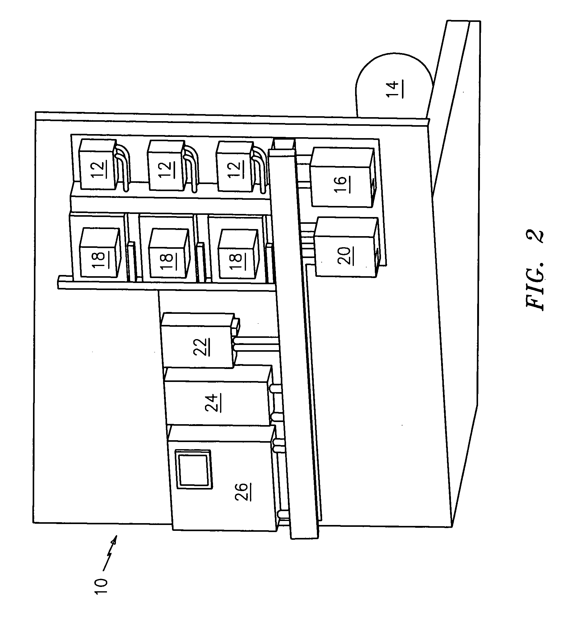
[0036] Referring now to FIG. 2, a more preferred embodiment of the modular regenerative fuel cell system of the present invention is shown generally at 10. System 10, which is rack-mounted, basically comprises: [0037] (a) electrolysis cell stack m...


PUM


Abstract

A modular, regenerative fuel cell system that includes a plurality of dedicated or reversible electrochemical cell stack modules, where each such module is devoid of major fluid systems, is provided. The inventive system allows a user to specifically and effectively tailor the system to the demands of a particular application. If additional electrolysis capability and/or additional power are needed, only electrolysis cell stack modules and/or fuel cell stack modules are added to the system. The use of unnecessary or duplicative support equipment is avoided thereby rendering this system more cost effective and efficient.

Description

RELATED APPLICATION [0001] This application claims priority from U.S. Provisional Patent Application Ser. No. 60 / 667,392, filed Mar. 31, 2005.FIELD OF THE INVENTION [0002] The present invention generally relates to a power generation and energy storage system, and more particularly relates to a modular regenerative fuel cell system. BACKGROUND AND SUMMARY OF THE INVENTION [0003] Regenerative fuel cell systems in which one or more electrochemical cells are utilized to both electrolyze water to produce hydrogen and oxygen, and to produce electricity by converting hydrogen and oxygen back into water, are known. These systems, which may be used with either renewable or non-renewable, grid connected or off-grid power sources, offer a means for storing energy to be used during periods when primary power from one of these sources is unavailable, and are constructed as either unitary or modular structures, with the modular design allowing for flexibility in, among other things, shipping, in...

Claims


Application Information

Patent Timeline
IPC IPC(8): H01M8/18H01M8/24H01M8/04
CPCC25B9/18H01M8/04201H01M8/0432H01M8/0438H01M8/0444H01M8/04753Y02E60/528H01M8/04947H01M8/0656H01M8/186H01M8/249H01M16/006H01M8/0494Y02E60/50Y02E60/10C25B9/70
Inventor SMITH, WILLIAM F.
Owner SMITH & WESSON
Why Eureka
Try Eureka