
Near-infrared transillumination for the imaging of early dental decay

a dental decay and near-infrared technology, applied in the field of dental caries detection by near-infrared transillumination, can solve the problems of occlusal lesions, root caries, secondary decay around composite restorations, cracks and defects in tooth enamel,

Inactive Publication Date: 2006-10-05
RGT UNIV OF CALIFORNIA
View PDF20 Cites 189 Cited by
  • Summary
  • Abstract
  • Description
  • Claims
  • Application Information

AI Technical Summary

Benefits of technology

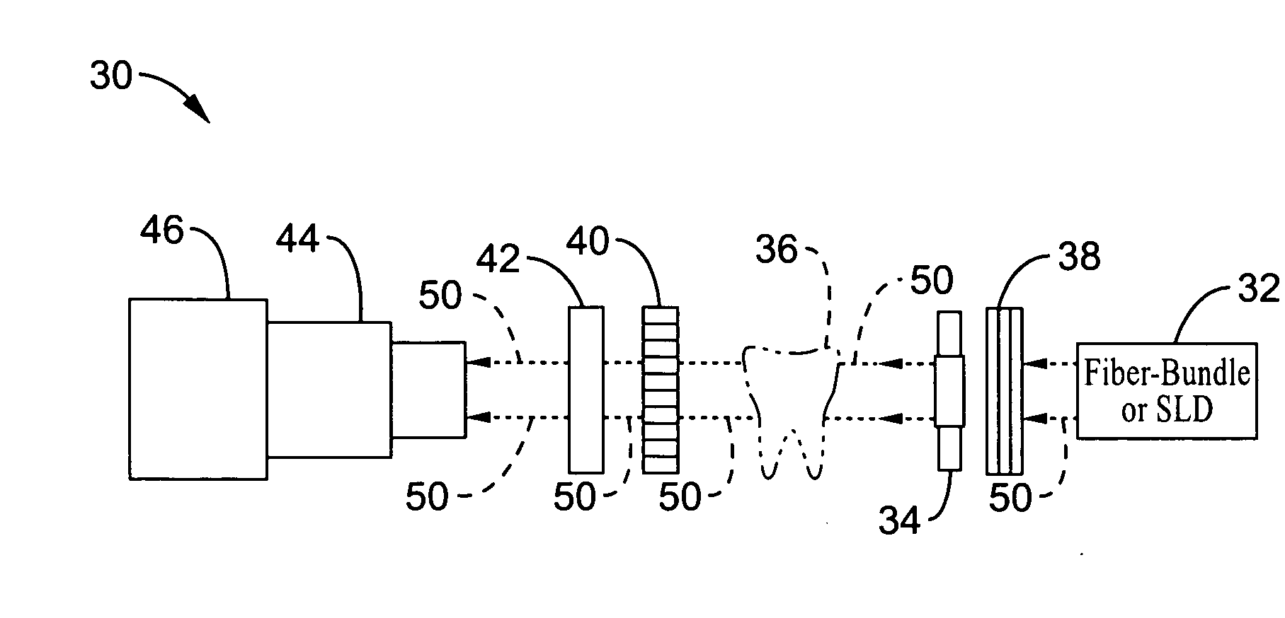
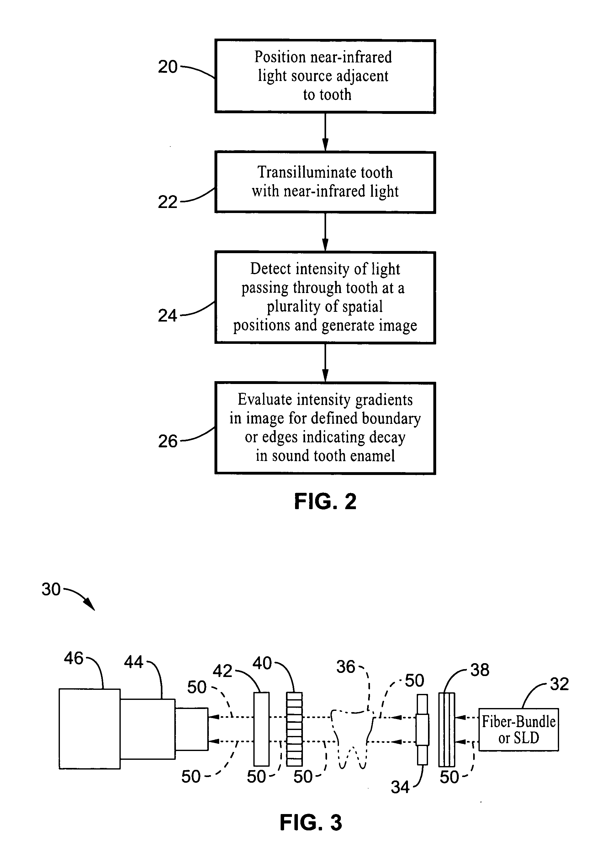
The present invention provides a system and method for detecting, diagnosing, and imaging dental tissue anomalies, such as early caries lesions, root caries, and cracks in dental restorations. The invention uses near-infrared light to transilluminate teeth and detect changes in mineralization of dental hard tissues with high resolution. The system includes a near-infrared light source and an imaging device for detecting the intensity of light passing through the tooth. The invention can be used for the detection and monitoring of dental anomalies and can help improve dental diagnosis and treatment.

Problems solved by technology

In addition, occlusal lesions, root caries, secondary decay around composite restorations, and cracks and defects in the tooth enamel can be seen.

Method used


Image

  • Near-infrared transillumination for the imaging of early dental decay
  • Near-infrared transillumination for the imaging of early dental decay
  • Near-infrared transillumination for the imaging of early dental decay

Examples


example 1

Sample Preparation

[0071] Thirty plano-parallel sections of enamel of various thicknesses (2-mm, 3-mm, 4-mm, 5-mm, 6-mm, and 6.75-mm) were prepared from non-carious human teeth. These sections were stored in a moist environment to preserve tissue hydration with 0.1% thymol added to prevent bacterial growth. Uniform scattering phantoms simulating dental decay were produced midway through each section by drilling 1-mm diameter×1.2-mm deep cavities in the proximal region of each sample and filling the cavities with hydroxyapatite paste. A thin layer of unfilled composite resin was applied to the outside of the filled cavity to seal the hydroxyapatite within the prepared tooth cavity.

NIR Imaging

[0072] Both a 150-watt halogen lamp, Visar™ (Den-Mat, Santa Maria, Calif.), and a 1310-nm superluminescent diode (SLD) with an output power of 3.5 mW and a bandwidth of 25-30 nm, Model QSDM-1300-5 (Qphotonics Inc., Chesapeake, Va.) were separately used as the illumination source.

[0073] Model K...


PUM


Abstract

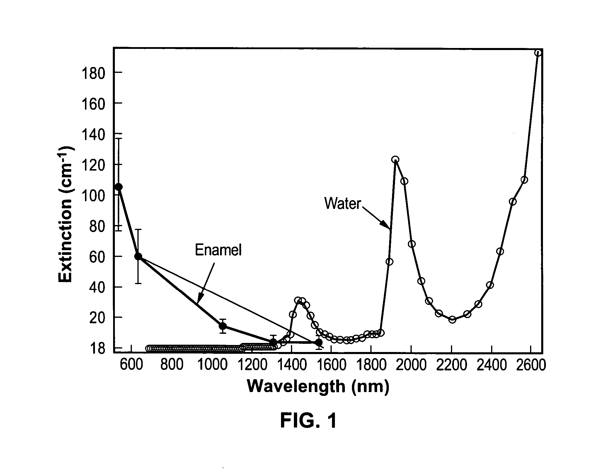
A method for detecting tooth decay and other tooth anomalies wherein a tooth is transilluminated with a near-infrared light source preferably in the range from approximately 795-nm to approximately 1600-nm, more preferably in the range from approximately 830-nm to approximately 1550-nm, more preferably in the range from approximately 1285-nm to approximately 1335-nm, and more preferably at a wavelength of approximately 1310-nm, and the light passing through the tooth is imaged for determining an area of decay in the tooth. The light source is a fiber-optic bundle coupled to a halogen lamp or more preferably a superluminescent diode, and the imaging device is preferably a CCD camera or a focal plane array (FPA).

Description

CROSS-REFERENCE TO RELATED APPLICATIONS [0001] This application claims priority from, and is a 35 U.S.C. § 111(a) continuation of, co-pending PCT international application serial number PCT / US2004 / 025872, filed on Aug. 6, 2004, which designates the U.S., incorporated herein by reference in its entirety, which claims priority from U.S. provisional application Ser. No. 60 / 493,569, filed on Aug. 8, 2003, the entirety of which is herein incorporated by reference. [0002] This application is related to PCT International Publication Numbers WO 2005 / 013843 A2 and WO 2005 / 013843 A3, each of which is incorporated herein by reference in its entirety. INCORPORATION-BY-REFERENCE OF MATERIAL SUBMITTED ON A COMPACT DISC [0003] Not ApplicableSTATEMENT REGARDING FEDERALLY SPONSORED RESEARCH OR DEVELOPMENT [0004] This invention was made with Government support under Grant No. 1-R01 DE14698 and Grant No. T32 DE07306-07 awarded by NIH / NICDR. The Government has certain rights in this invention.BACKGROUN...

Claims


Application Information

Patent Timeline
Patent Type & Authority Applications(United States)
IPC IPC(8): A61C5/00A61B5/117A61B5/00A61C
CPCA61B5/0088
Inventor FRIED, DANIELJONES, ROBERT
Owner RGT UNIV OF CALIFORNIA
Learn More