Light emitting device, super-luminescent diode, and projector
- Summary
- Abstract
- Description
- Claims
- Application Information
AI Technical Summary
Benefits of technology
Problems solved by technology
Method used
Image

Examples
first embodiment
1. First Embodiment
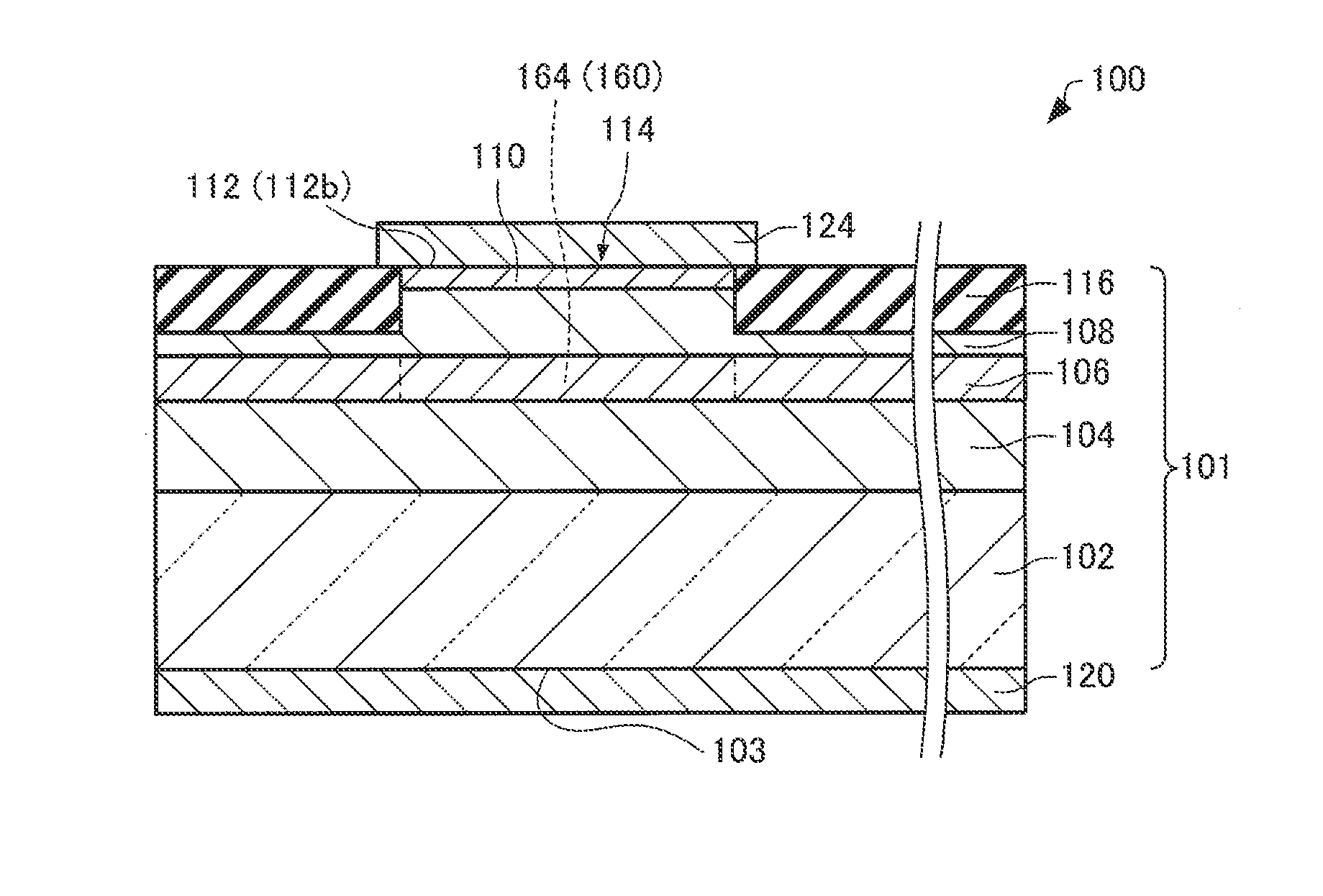
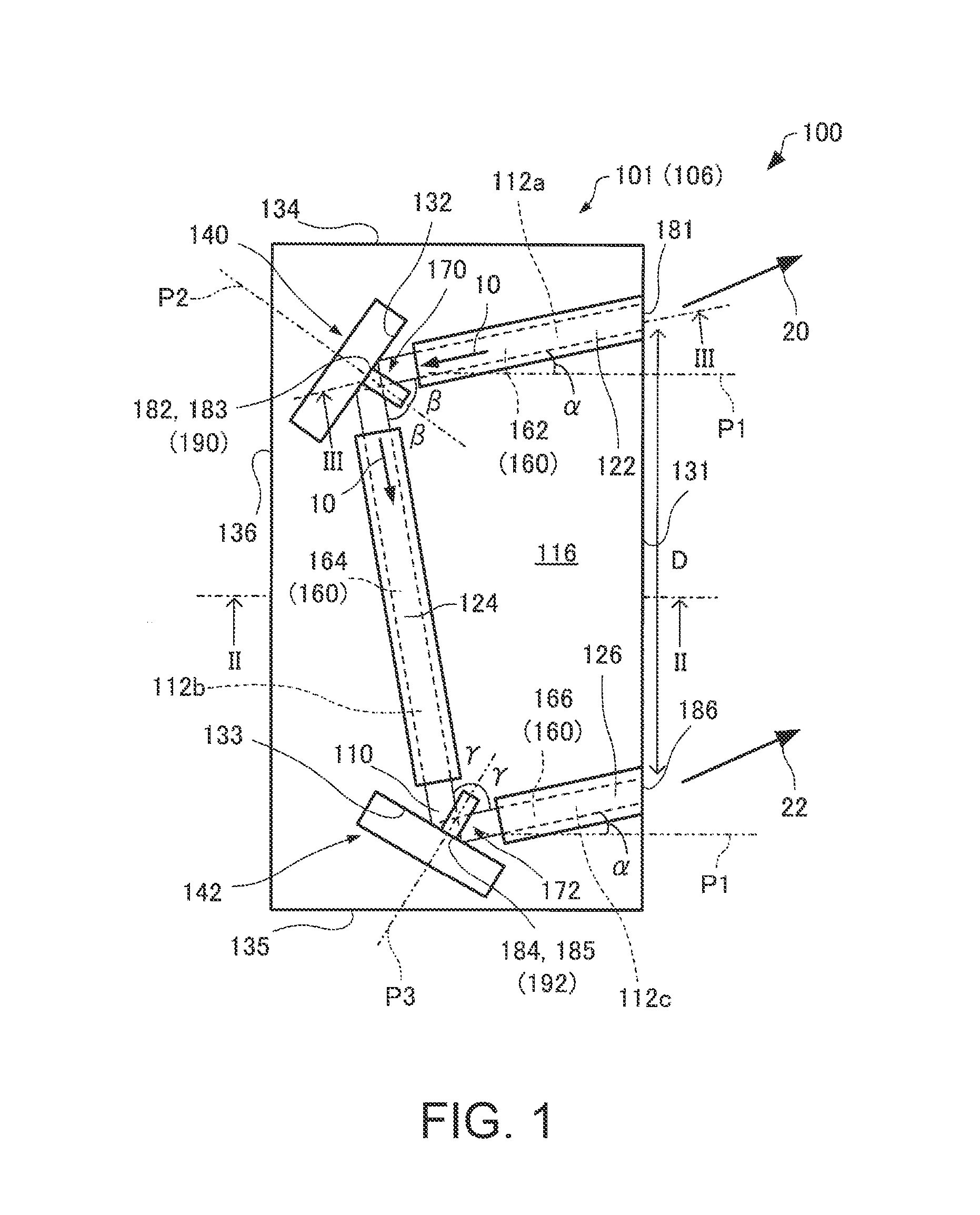
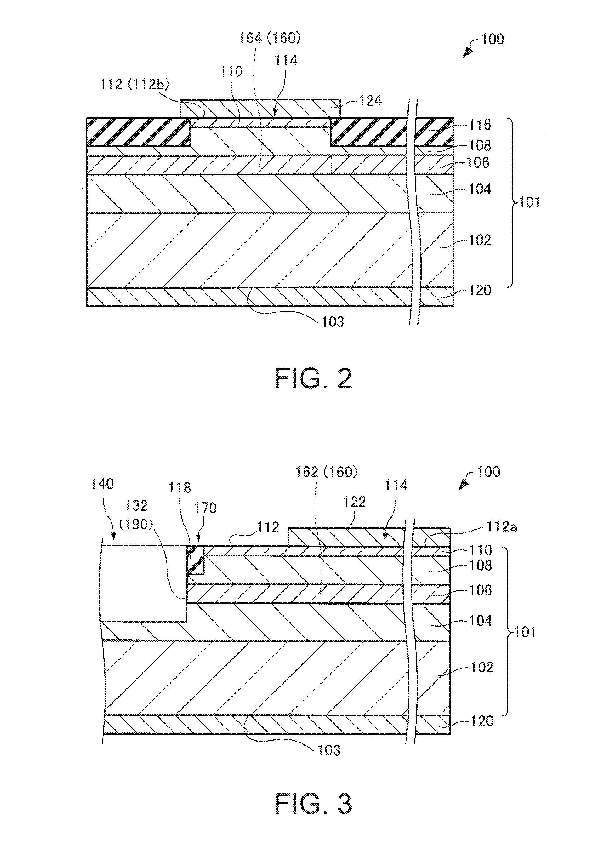
[0055]Firstly, a light emitting device according to a first embodiment will be explained with reference to the accompanying drawings. FIG. 1 is a plan view schematically showing the light emitting device 100 according to the first embodiment. FIG. 2 is a cross-sectional view along the line II-II shown in FIG. 1, and schematically shows the light emitting device 100 according to the first embodiment. FIG. 3 is a cross-sectional view along the line III-III shown in FIG. 1, and schematically shows the light emitting device 100 according to the first embodiment.
[0056]The case in which the light emitting device 100 is an SLD of the InGaAlP type (red) will be explained below. Unlike the semiconductor laser, in the SLD, the laser oscillation can be prevented by suppressing formation of the resonator due to the end surface reflection. Therefore, the speckle noise can be reduced.
[0057]As shown in FIGS. 1 to 3, the light emitting device 100 include...
first modified example
1.3.1. First Modified Example
[0151]Then, a light emitting device according to a first modified example of the first embodiment will be explained with reference to the accompanying drawings. FIG. 11 is a plan view schematically showing a light emitting device 200 according to the first modified example of the first embodiment.
[0152]Hereinafter, in the light emitting device 200 according to the first modified example of the first embodiment, the members having the same functions as those of the constituent members of the light emitting device 100 according to the first embodiment will be denoted by the same reference symbols, and the detailed explanation thereof will be omitted. The same applies to a light emitting device 300 according to a second modified example of the first embodiment described later.
[0153]As shown in FIG. 1, in the light emitting device 100, the current is injected into the first portion 162 of the optical waveguide 160 only by the electrodes 120, 122, the current...
second modified example
1.3.2. Second Modified Example
[0159]Then, a light emitting device according to a second modified example of the first embodiment will be explained with reference to the accompanying drawings. FIG. 12 is a plan view schematically showing the light emitting device 300 according to the second modified example of the first embodiment.
[0160]As shown in FIG. 1, in the light emitting device 100, the single optical waveguide 160 is disposed. In contrast, in the light emitting device 300, a plurality of optical waveguides 160 are disposed as shown in FIG. 12. Although the two optical waveguides 160 are provided in the example shown in the drawing, the number of the optical waveguides 160 is not particularly limited providing the number is equal to or larger than two. The plurality of optical waveguides 160 are arranged in a direction perpendicular to the perpendicular P1 of the first side surface 131. In the example shown in the drawing, the first exit section 181 and the second exit section...
PUM
 Abstract
Description
Claims
Application Information
 - R&D
- Intellectual Property
- Life Sciences
- Materials
- Tech Scout
- Unparalleled Data Quality
- Higher Quality Content
- 60% Fewer Hallucinations
Browse by: Latest US Patents, China's latest patents, Technical Efficacy Thesaurus, Application Domain, Technology Topic, Popular Technical Reports.
© 2025 PatSnap. All rights reserved.Legal|Privacy policy|Modern Slavery Act Transparency Statement|Sitemap|About US| Contact US: help@patsnap.com