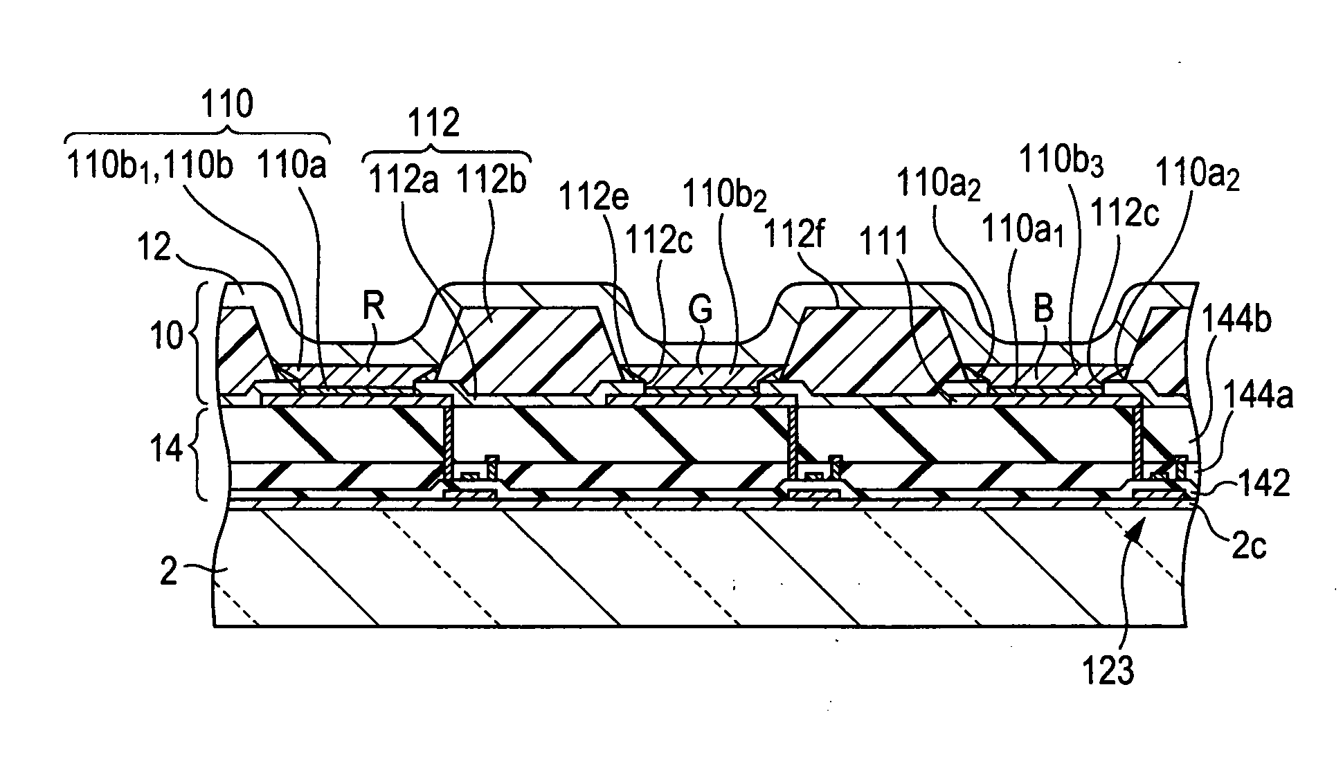
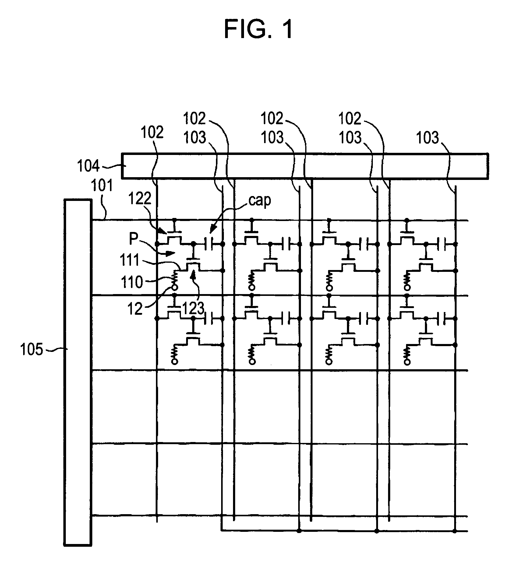
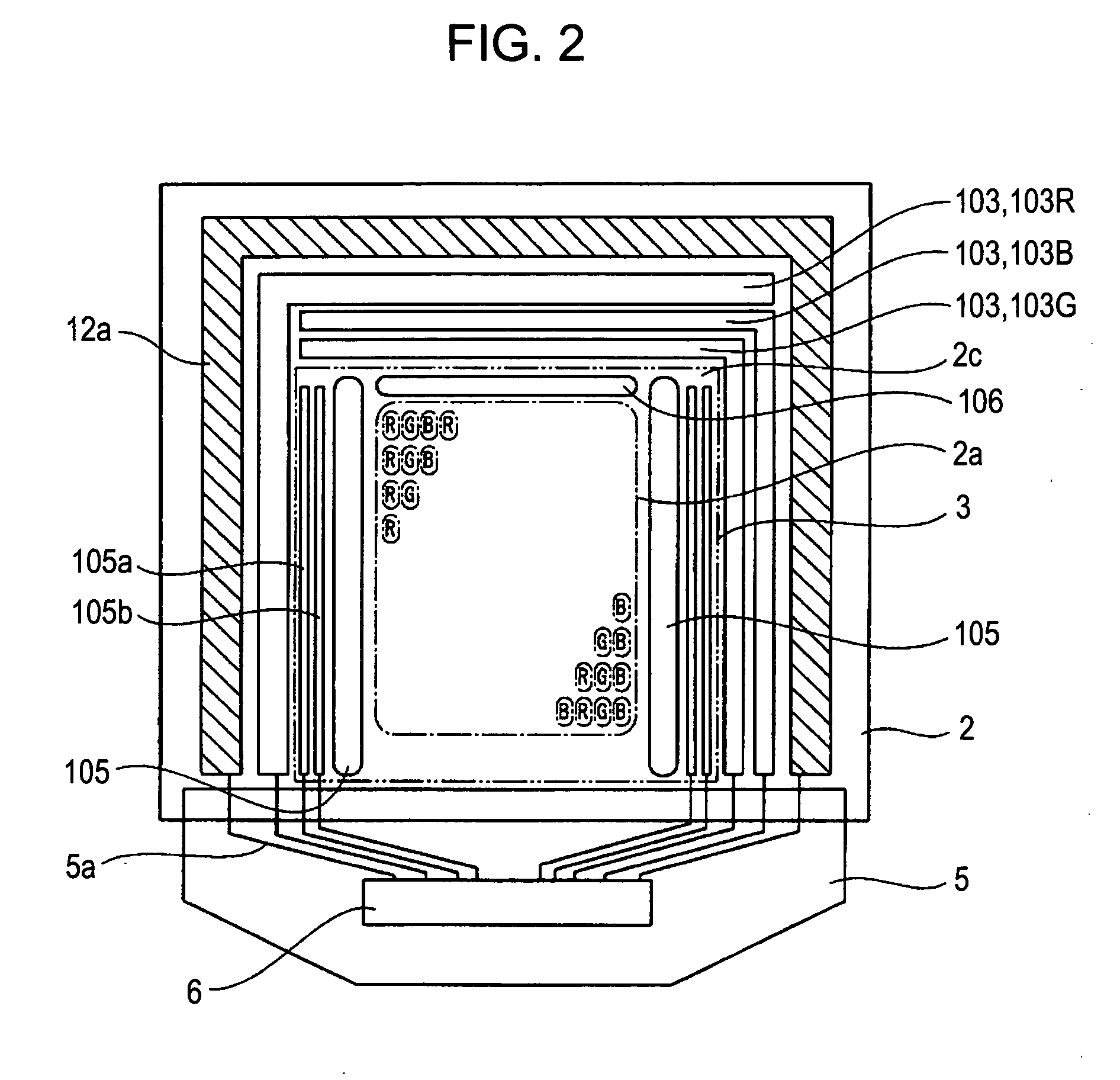
Method of manufacturing organic electroluminescent device and method of manufacturing device
a manufacturing method and electroluminescent technology, applied in static indicating devices, instruments, coatings, etc., can solve the problems of low flatness of functional layers to be formed, excessive lyophobic properties with respect to partition walls, and deterioration of light-emitting characteristics, so as to improve the flatness of functional layers formed by drying liquid compositions. , the effect of high flatness
- Summary
- Abstract
- Description
- Claims
- Application Information
AI Technical Summary
Benefits of technology
Problems solved by technology
Method used
Image

Examples
embodiments
[0121] Hereinafter, the embodiments and the comparison examples have been examined in order to confirm the effect according to the aspects of the invention. That is, in the light-emitting layer forming process illustrated in the above-mentioned embodiments, the different solvent is used in each case, and the organic EL device according to each of the embodiments and the comparison examples has been manufactured. As shown in FIG. 11, the organic EL device according to each of the first comparison example and the first to fourth embodiments has been manufactured using the solvent in which the composition ratio (volume ratio) of fluorobenzene and trimethybenzene is different.
[0122] As shown in FIG. 11, in each of the organic EL devices which have been manufactured, the film shape of the light-emitting layer 110b is observed by the microscope, and a film maximum height y and a film minimum height x are calculated, as shown in FIGS. 12A and 12B. FIG. 12A illustrates a shape where the fi...
PUM
| Property | Measurement | Unit |
|---|---|---|
| thickness | aaaaa | aaaaa |
| thickness | aaaaa | aaaaa |
| thickness | aaaaa | aaaaa |
Abstract
Description
Claims
Application Information
 - R&D
- Intellectual Property
- Life Sciences
- Materials
- Tech Scout
- Unparalleled Data Quality
- Higher Quality Content
- 60% Fewer Hallucinations
Browse by: Latest US Patents, China's latest patents, Technical Efficacy Thesaurus, Application Domain, Technology Topic, Popular Technical Reports.
© 2025 PatSnap. All rights reserved.Legal|Privacy policy|Modern Slavery Act Transparency Statement|Sitemap|About US| Contact US: help@patsnap.com