Subarachnoid epidural shunt

Inactive Publication Date: 2006-10-05
GLENN BRADLEY J
View PDF7 Cites 39 Cited by
  • Summary
  • Abstract
  • Description
  • Claims
  • Application Information

AI Technical Summary

Benefits of technology

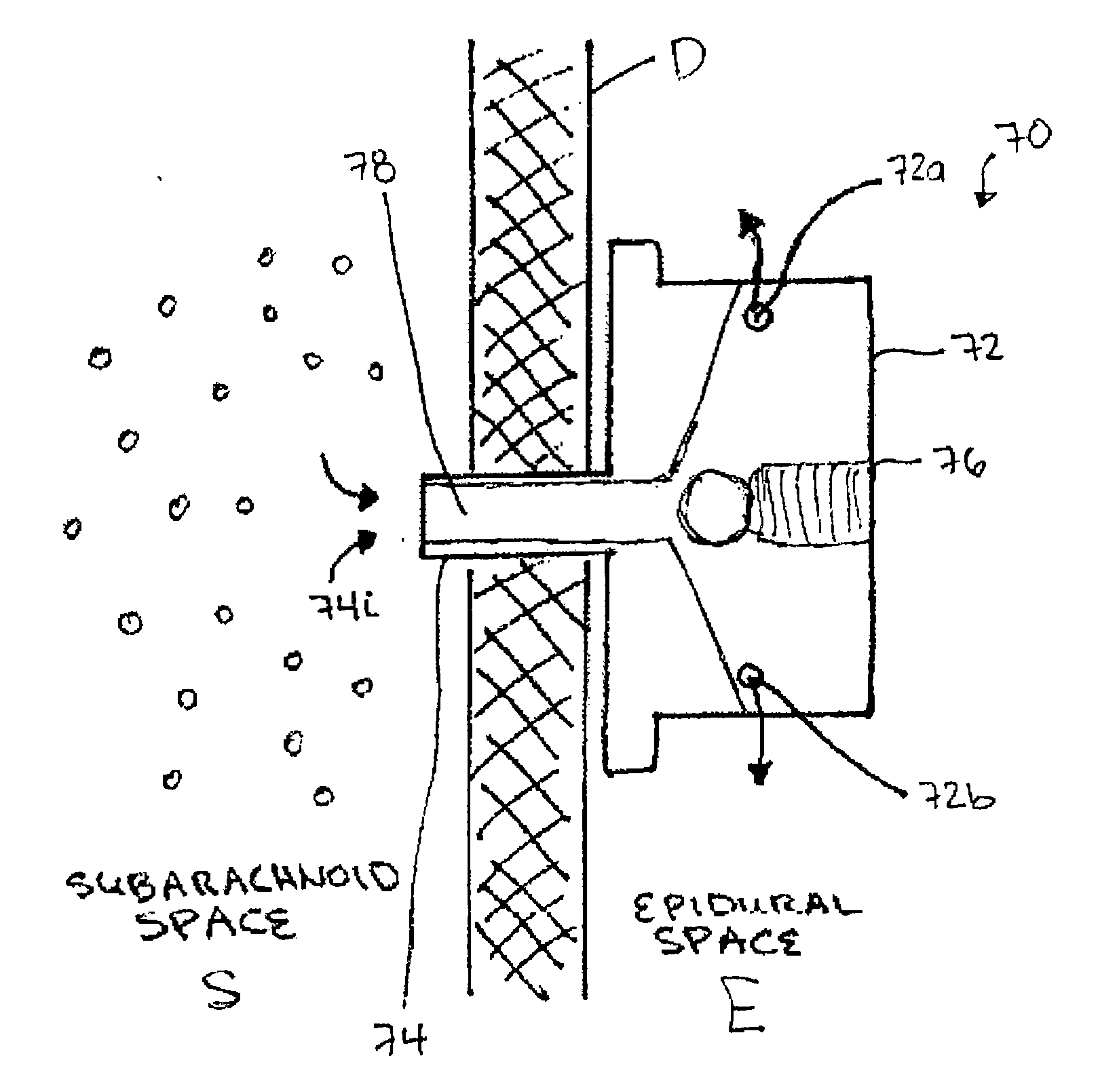
[0009] The housing can have a variety of configurations, but in one embodiment the housing can include an elongate member extending therefrom and adapted to be disposed within a bone hole. The elongate member can have a variety of configurations, and it can include a first lumen in fluid communication with the fluid inlet port, and optionally a second lumen in fluid communication with the fluid outlet port. The elongate member can include other features, such as an external surface that is adapted to facilitate bone in-growth into the elongate member. For example, the elongate member can include bone-engaging surface features or a surface coating. In other embodiments, the device can also include a sleeve that is removably disposed around the elongate member and that is adapted to be disposed within a bone hole to anchor the elongate member within the bone hole. The sleeve can include a flange formed on a terminal end thereof and adapted to abut against a bone surface. The sleeve can also include a mating element formed on an inner surface thereof and adapted to removably mate to a complementary mating element formed on an outer surface of the elongate member.
[0010] In another embodiment, the housing can include a central portion that is adapted to be disposed within a lumen, and opposed first and second ends that are adapted to be positioned adjacent to opposed ends of the lumen to anchor the central portion within the lumen. The fluid inlet port can be formed in the first end of the housing and the fluid outlet port can be formed in the second end of the housing. The central portion can have a variety of configurations, but in one exemplary embodiment it can have a substantially cylindrical shape that is configured to be disposed within a substantially cylindrical lumen. The flow control component can be disposed within an inner lumen or bore formed in the central portion, or the bore can form the flow control component and it can have a diameter that is effective to control fluid flow therethrough. The first and second ends of the housing can also have a variety of configurations, but in one embodiment the first and second ends of the housing can be expandable.
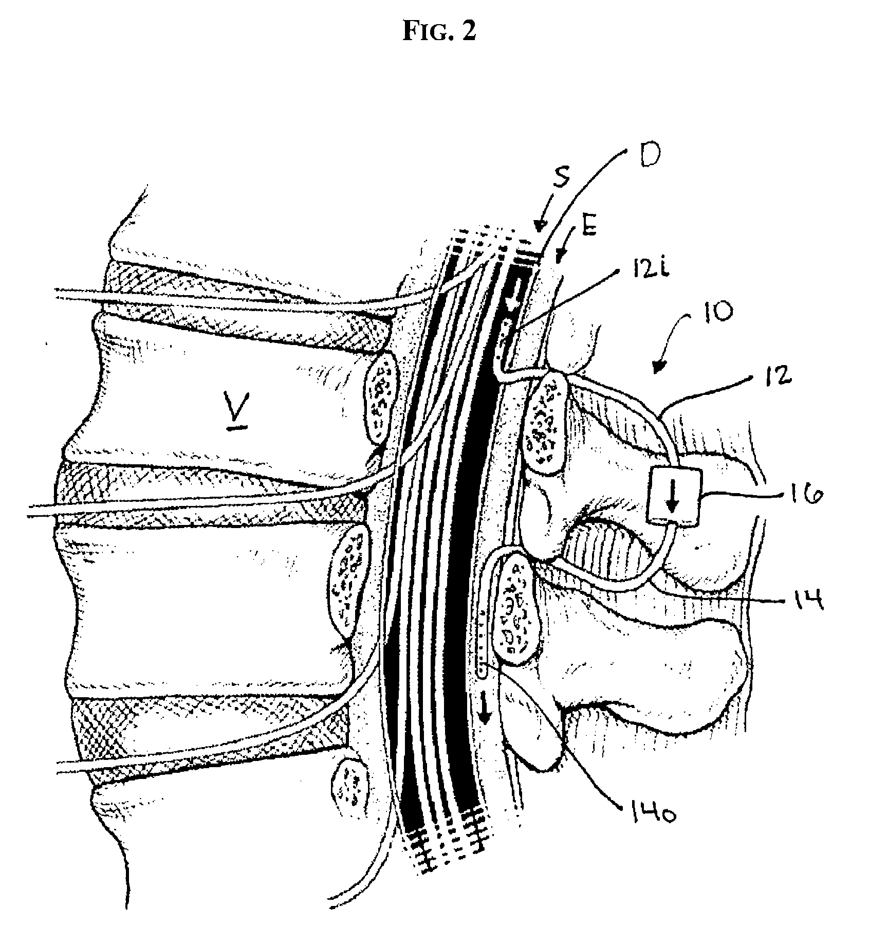
[0011] In other aspects, a shunt system is provided having a shunt with first and second catheters and a flow control component coupled therebetween for controlling fluid flow from the first catheter to the second catheter. The system also includes a dual-lumen cannula having first and second lumens extending therethrough for respectively receiving the first and second catheters. The first lumen can have an opening that is positioned a distance apart from an opening in the second lumen such that the opening in the first lumen can be positioned to receive fluid from a subarachnoid space in a spinal column and the opening in the second lumen can be positioned to deliver fluid to an epidural space in a spinal column. In an exemplary embodiment, a portion of the first lumen adjacent to the opening is curved to guide the first catheter into the subarachnoid space, and a portion of the second lumen adjacent to the opening is curved to guide the second catheter into the epidural space.
[0012] Methods for shunting fluid are also provided, and in one embodiment the method can include positioning an inlet port of a shunt to receive fluid from a subarachnoid

Problems solved by technology

In a patient suffering from hydrocephalus, the cerebrospinal fluid is not absorbed in this manner, but instead accumulates in the ventricles of the patient's brain and can lead to serious medical conditions.
With NPH it is believed that the ventricles enlarge to handle the increased volume of the CSF, and the compression of the brain from within by the fluid-filled ventricles destroys or damages brain tissue causing some ofthe symptoms.
Vascular shunts functioned very well, but they were prone to multiple problems including early and late infection, as well as rare, potentially fatal heart failure due to blockage of blood vessels within the lu

Method used


Image

  • Subarachnoid epidural shunt
  • Subarachnoid epidural shunt
  • Subarachnoid epidural shunt

Examples


Embodiment Construction

[0038] Certain exemplary embodiments will now be described to provide an overall understanding of the principles of the structure, function, manufacture, and use of the devices and methods disclosed herein. One or more examples of these embodiments are illustrated in the accompanying drawings. Those of ordinary skill in the art will understand that the devices and methods specifically described herein and illustrated in the accompanying drawings are non-limiting exemplary embodiments and that the scope of the present invention is defined solely by the claims. The features illustrated or described in connection with one exemplary embodiment may be combined with the features of other embodiments. Such modifications and variations are intended to be included within the scope of the present invention.

[0039] The present invention provides methods and devices for shunting fluid to treat hydrocephalous, and in particular NPH, or Alzheimer's, Idiopathic Intracranial Hypertension (IIH), or ...


PUM


Abstract

Methods and devices are provided for shunting fluid to treat hydrocephalous, and in particular for treating normal pressure hydrocephalous, or Alzheimer's, Idiopathic Intracranial Hypertension (IIH), or any other condition in which it is necessary to drain and/or cleanse CSF. The methods and devices utilize a shunt having an inlet port, and outlet port, and a flow control component for controlling fluid flow from the inlet port to the outlet port. The shunt can be implanted at a location along or within a patient's spinal column. In one exemplary embodiment, an inlet port of a shunt can be implanted within the subarachnoid space, and an outlet port of a shunt can be implanted at a drainage site. In certain exemplary embodiments, the cerebrospinal fluid is drained into the epidural space.

Description

CROSS-REFERENCE TO RELATED APPLICATIONS [0001] The present invention claims priority to U.S. Provisional Application No. 60 / 668,111, filed on Apr. 5, 2005 and entitled “Subarachnoid-Epidural Shunt,” and U.S. Provisional Application No. 60 / 703,470, filed on Jul. 29, 2005 and entitled “Subarachnoid-Epidural Shunt and Improved CSF Diversion Devices and Methods,” which are hereby incorporated by reference in their entireties.FIELD OF THE INVENTION [0002] The present invention relates to methods and devices for shunting cerebrospinal fluid. BACKGROUND OF THE INVENTION [0003] Many conditions benefit from shunting, removal, or cleansing of CSF, including hydrocephalus, pseudotumor cerebri (Idiopathic Intracranial Hypertension, IIH), and Alzheimer's disease. Hydrocephalus, for example, is a condition afflicting patients who are unable to regulate cerebrospinal fluid flow through their body's own natural pathways. Produced by the ventricular system, cerebrospinal fluid (CSF) is normally abso...

Claims


Application Information

Patent Timeline
IPC IPC(8): A61M5/00A61F2/04
CPCA61M27/006
Inventor GLENN, BRADLEY J.
Owner GLENN BRADLEY J
Why Eureka
Try Eureka