
Eureka
For R&D, Eureka makes reading and utilizing patents & technical documents easy.
Eureka AIR
Designed for self-driven R&D workflows. Generate viable solutions, solve complex R&D challenges, empower your innovation with AI.

Eureka Materials
Designed for material experts only. Revolutionize your material R&D, from search, analyze, to developing new materials.

TechResearch
Generate reliable direction feasibility study reports for your R&D in just a few steps.

TechSeek
Discover and master advanced knowledge NOW. Basics, ideas, possibilities, all at once.

TechMind
As an expert in R&D Theories, TechMind can generates customized viable solutions instantly.

TechRisk
Analyze your overall solution with one click, know your potential R&D risks in advance.

TechMonitor
Get weekly tech updates, stay abreast of the latest tech innovations and key insights.
Stowable table
- Summary
- Abstract
- Description
- Claims
- Application Information
AI Technical Summary
Benefits of technology
Problems solved by technology
Method used
Image

Examples
first embodiment
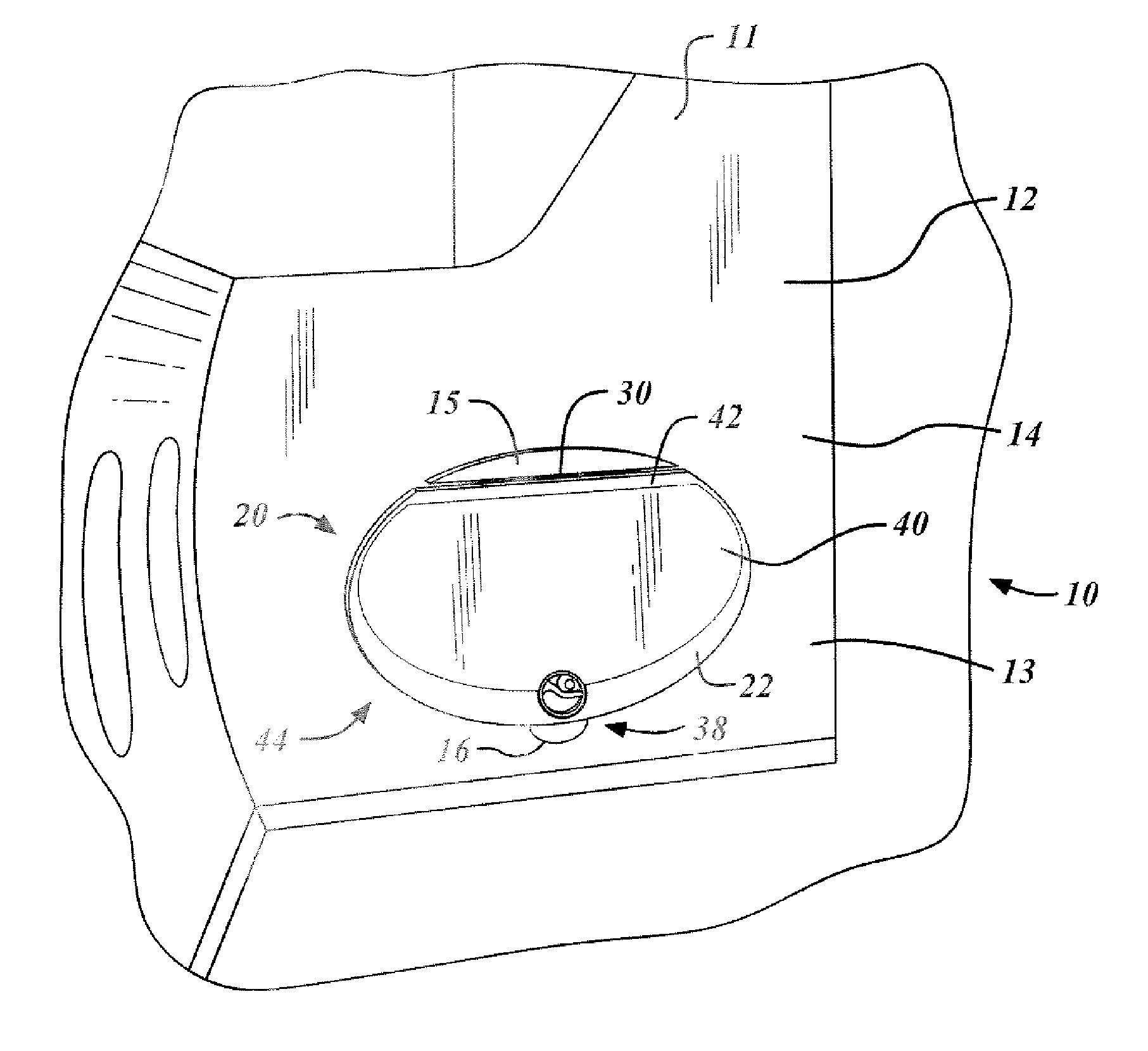
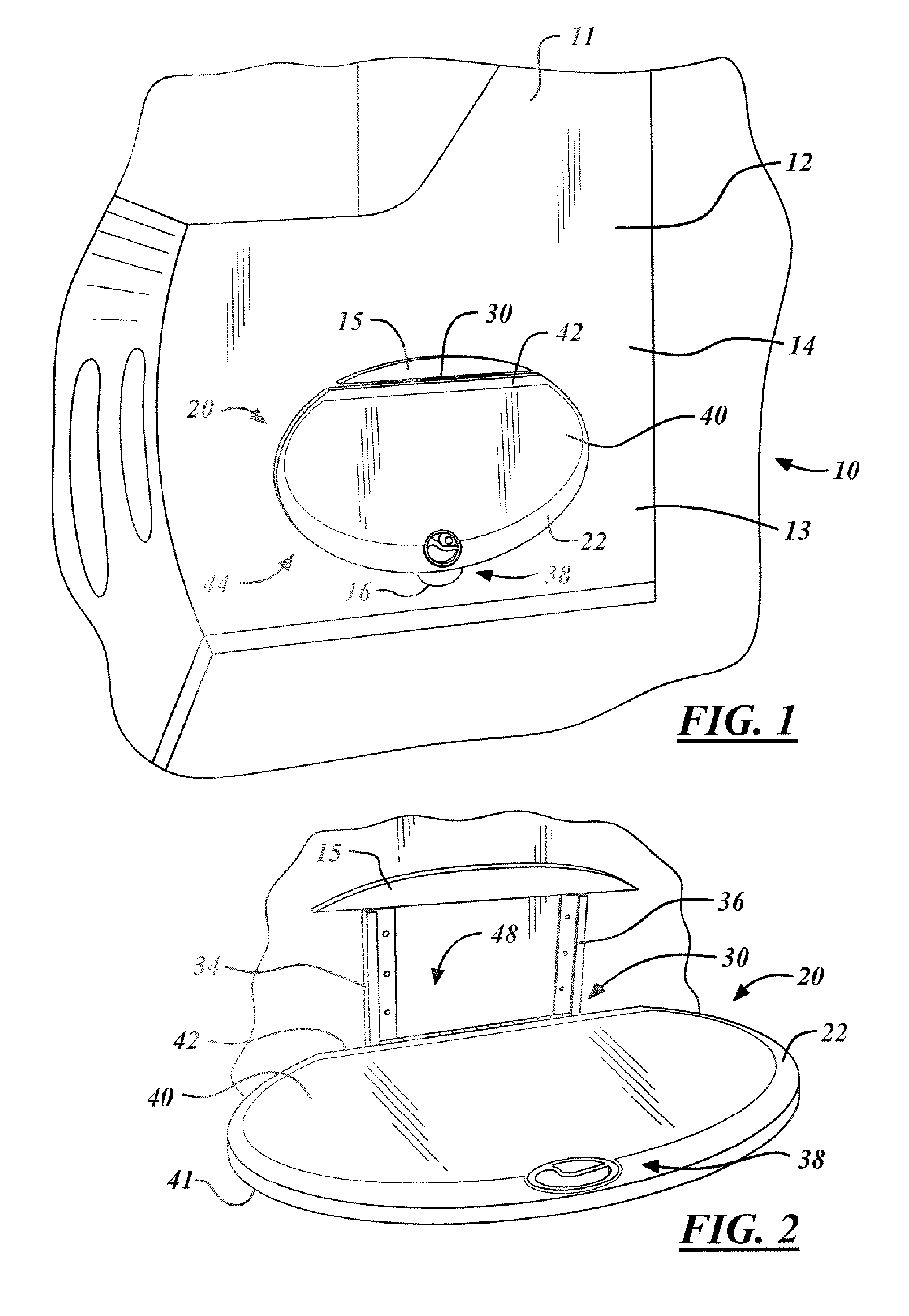
[0022]FIG. 1 shows a partial isomeric view of a stowable surface 20 being used to advantage in a stowed position 47 on an aircraft 10 in accordance with the present invention. Passenger aircrafts have bulkheads, partitions, and walls suitable to support tables that are attached and self-storing thereon. A wall 11 on the aircraft 10 typically includes a front side 12 that may be proportioned into a lower portion 13 and a mid portion 14 to which the stowable surface 20 may be attached.
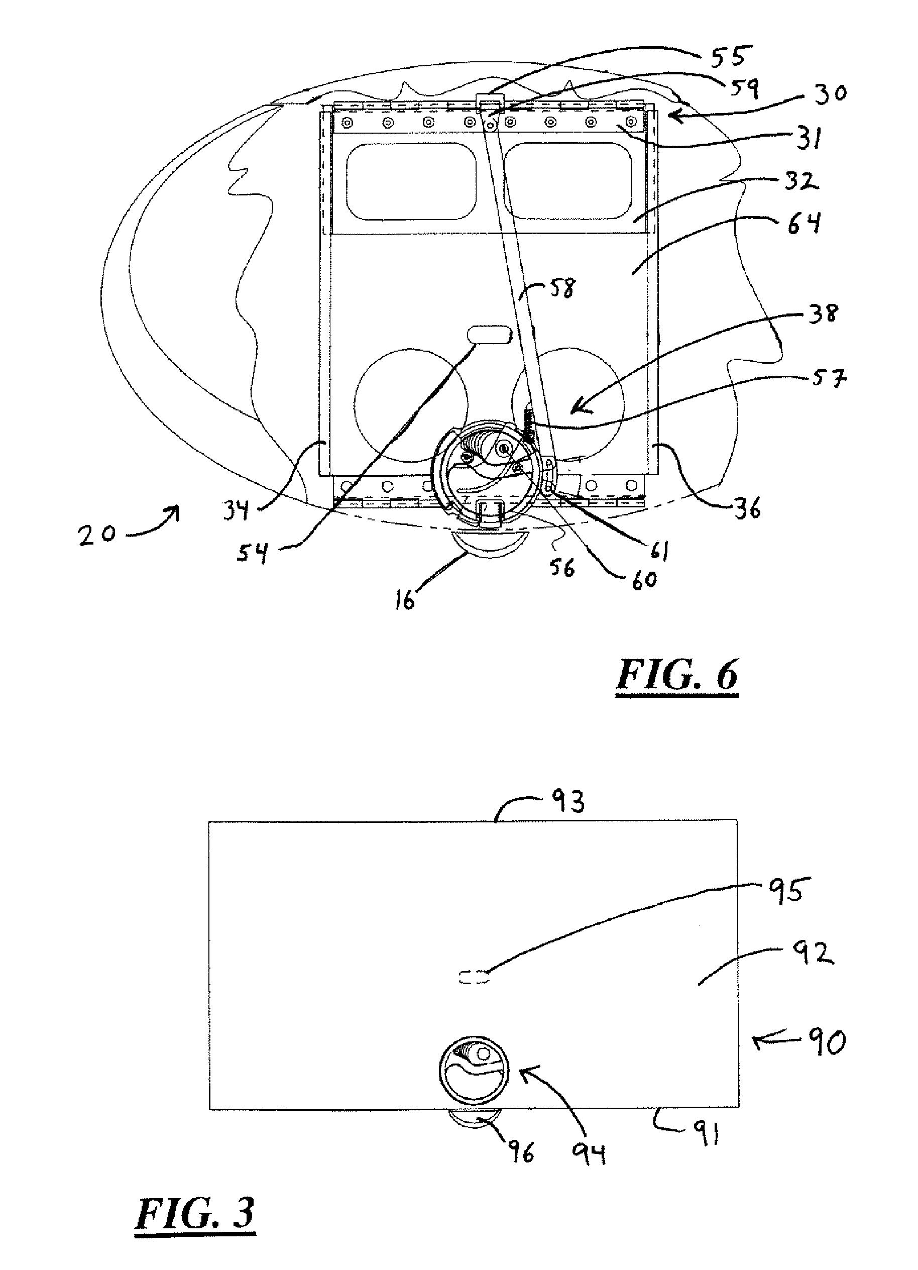
[0023] Simultaneous reference may be made to FIGS. 4, 6 and 10, which show the first embodiment of the invention in FIG. 1 being used to advantage. FIG. 4 shows a front view of a stowable surface in accordance with the first embodiment of the present invention. FIG. 6 shows a partial cross-sectional view of the stowable surface of FIG. 4. FIG. 10 shows a partial cross-sectional view of the stowable surface of FIG. 4. The stowable surface 20, shown in a stowed position 47 in FIG. 1, includes a first pivot...
second embodiment
[0035]FIG. 3 shows a front view of a stowable table 90 in accordance with the present invention being used to advantage. The stowable table 90 includes a tabletop 91, a support bracket (not shown) and a back member (not shown). The tabletop 91 has a top surface 92, a bottom surface and an end 93. The support bracket includes an upper end and a lower end, wherein the upper end is pivotally connected to the bottom surface of the tabletop 92.
[0036] The back member includes a bottom end, a top end, a back side and a front side, wherein the front side extends between the bottom end and the top end of the back member. The lower end of the support bracket is pivotally connected to the bottom end of the back member and the end 93 of the tabletop 91 is positionably connected to the front side of the back member, thereby allowing the tabletop 93 to be positioned between a stowed position and a deployed position when a latch assembly 94 is actuated. Also, the stowable table 90 of this embodime...
third embodiment
[0039]FIG. 9A is a partial cross-sectional side view of a stowable platform 70 in a stowed position in accordance with the present invention being used to advantage. A stowable platform includes a first member 71, a second member 72 and a third member 73. The first member 71 has a first side 74, a second side 75 and a first end 76. The second member 72 has an upper end 77 and a lower end 78, whereby the upper end 77 is pivotally connected to the second side 75 of the first member 71. The third member 73 has a bottom end 79, a top end 80, a back side 81 and a front side 82, where the front side 82 extends between the bottom end 79 and the top end 80. The lower end 78 of the second member 72 is pivotally connected to the bottom end 79 of the third member 73, thereby, allowing the first end 76 of the first member 71 to be positionably connected to the front side 82 of the third member 73 between a stowed position and a deployed position.
[0040] The pivotal connection between the first m...
PUM
 Abstract
Description
Claims
Application Information
 - R&D Engineer
- R&D Manager
- IP Professional
- Industry Leading Data Capabilities
- Powerful AI technology
- Patent DNA Extraction
Browse by: Latest US Patents, China's latest patents, Technical Efficacy Thesaurus, Application Domain, Technology Topic, Popular Technical Reports.
© 2024 PatSnap. All rights reserved.Legal|Privacy policy|Modern Slavery Act Transparency Statement|Sitemap|About US| Contact US: help@patsnap.com