Braking a vehicle in the context of an emergency stop

a technology for emergency stops and brakes, applied in brake systems, mechanical devices, transportation and packaging, etc., can solve problems such as discomfort and perception of jerks by drivers, and achieve the effect of increasing the proportion of the second braking system and reducing the proportion of the service brak

Inactive Publication Date: 2006-10-12
ROBERT BOSCH GMBH
View PDF3 Cites 19 Cited by
  • Summary
  • Abstract
  • Description
  • Claims
  • Application Information

AI Technical Summary

Benefits of technology

[0005] One important idea of the present invention is that of actuating the service brake and a second braking system (preferably a parking brake) at least at times simultaneously, and “cross-fading” the braking action of the service brake over to the second braking system, i.e. reducing the proportion of the service brake and increasing the proportion of the second braking system. This has the substantial advantage that a uniform, uninterrupted braking operation can be performed.
[0008] According to a preferred embodiment of the present invention, after initiation of an emergency stop at first only the positioning member of the service brake is actuated, provided the vehicle speed is above a predetermined threshold. Until the speed threshold is reached, the vehicle is decelerated exclusively by the service brake. After the speed threshold is reached, or if the vehicle speed was lower than the threshold value from the outset, the second braking system is then switched in and the vehicle is decelerated by both braking systems simultaneously. The braking effect of the service brake is reduced as the braking operation proceeds, and that of the second braking system increased. The result is, in particular, to rule out locking of the vehicle's wheels at high speed because of the action of the second braking system.
[0009] The function with which the braking effect of the service braking system is reduced, and that of the second braking system is increased, is preferably selected in such a way that the same or approximately the same total braking pressure is exerted at each point in time during the braking operation. This has the substantial advantage that the braking behavior of the vehicle does not change.
[0010] The control system for the positioning members is preferably designed in such a way that the braking pressure exerted by the service brake decreases linearly and the braking pressure exerted by the second braking system rises linearly. The result is, in particular, to achieve a continuous profile for the total braking force.
[0011] According to a preferred embodiment of the present invention, during an emergency stop the vehicle is preferably braked to a standstill by both braking systems. The best braking effect can thereby be achieved. Once the vehicle is at a standstill, the parking brake is preferably set and the vehicle is prevented from rolling away.

Problems solved by technology

A perceptible jerk occurs upon release of the service brake and application of the parking brake, however, and is perceived by the driver as uncomfortable.

Method used


Image

  • Braking a vehicle in the context of an emergency stop
  • Braking a vehicle in the context of an emergency stop
  • Braking a vehicle in the context of an emergency stop

Examples


Embodiment Construction

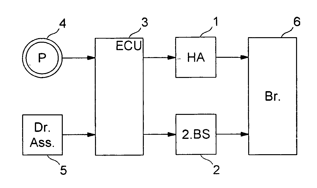
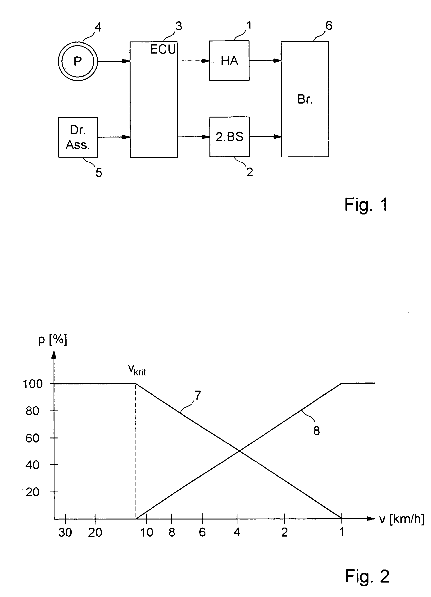
[0017]FIG. 1 is a block depiction of the important elements of an emergency stop system. In the present case that system encompasses two braking systems, namely a service brake having components 1, 3, and 6, and a second braking system independent thereof (e.g. a parking brake) having components 2, 3, and 6. Optionally, more than two braking systems could also be provided.

[0018] The service brake encompasses a positioning member 1 such as, for example, a hydraulic pump, with which a wheel brake 6 can be actuated. Second braking system 2, 3, 6 encompasses a positioning member 2 such as, for example, an electric motor, with which the braking pressure acting on wheel brake 6 can be varied. In the present example both positioning members 1, 2 act on the same braking apparatus, namely the brake caliper of a wheel brake 6. Optionally, positioning members 1, 2 can also act on different braking apparatuses, for example positioning member 1 on the brake caliper of a disc brake and positioni...


PUM


Abstract

A method for braking a vehicle in the context of an emergency stop with the aid of a service braking system and a second braking system. The braking operation can be carried out uniformly and continuously if a positioning member of the service braking system and a positioning member of the second braking system are actuated simultaneously, the braking pressure exerted by the positioning member of the service braking system being reduced in the course of the braking operation, and the braking pressure exerted by the positioning member of the second braking system being increased.

Description

FIELD OF THE INVENTION [0001] The present invention relates to a method for braking a vehicle in the context of an emergency stop, as well as a braking system having an emergency stop function. BACKGROUND INFORMATION [0002] Modern vehicles are more and more often being equipped with emergency stop apparatuses with which the vehicle can be braked in critical driving situations. Such systems usually encompass an operating element such as, for example, a pushbutton, that can be actuated by the driver in order to initiate an emergency stop. The emergency stop request is detected by a control unit connected to the operating element, which unit thereupon triggers a positioning member of the service braking system, such as e.g. a hydraulic pump, in order to build up pressure in the wheel brakes and decelerate the vehicle. Other vehicles additionally or alternatively encompass a driver assistance system such as, for example, a video monitoring system, which automatically initiates the emerg...

Claims


Application Information

Patent Timeline
IPC IPC(8): F16D65/14
CPCB60T17/18B60T2230/04B60T8/00B60T7/085B60T7/042F16H63/48
Inventor JAEGER, GABRIEL
Owner ROBERT BOSCH GMBH
Why Eureka
Try Eureka