Dual-channel deicing system for a rotary wing aircraft

a rotary wing aircraft and rotor system technology, applied in aircrafts, ground installations, transportation and packaging, etc., can solve the problems of reducing the service life of the aircraft, affecting the flight safety of the aircraft, so as to minimize the likelihood of melted ice refreezing

Active Publication Date: 2006-10-12
SIKORSKY AIRCRAFT CORP
View PDF20 Cites 44 Cited by
  • Summary
  • Abstract
  • Description
  • Claims
  • Application Information

AI Technical Summary

Benefits of technology

[0011] Each electric pulse train of a four-bladed, four-heating-element main rotor sequentially provides power to the heating elements in the designated blade set. The sequential order being the third electrothermal heating element, the first electrothermal heating element, the second electrothermal heating

Problems solved by technology

Rotary-wing aircraft may encounter atmospheric conditions that cause the formation of ice on rotor blades and other surfaces of the aircraft.
Accumulated ice, if not removed, can add weight to the aircraft and may alter the airfoil configuration causing undesirable flying characteristics.
Rotary wing aircraft rotor blades are particularly susceptible to icing and provide numerous

Method used


Image

  • Dual-channel deicing system for a rotary wing aircraft
  • Dual-channel deicing system for a rotary wing aircraft
  • Dual-channel deicing system for a rotary wing aircraft

Examples


Embodiment Construction

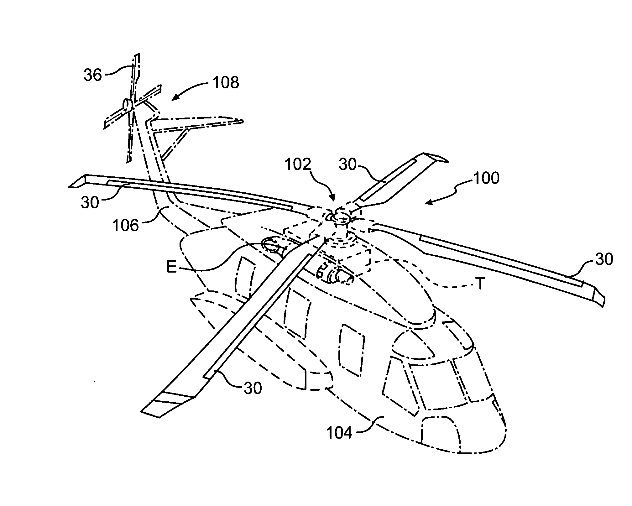
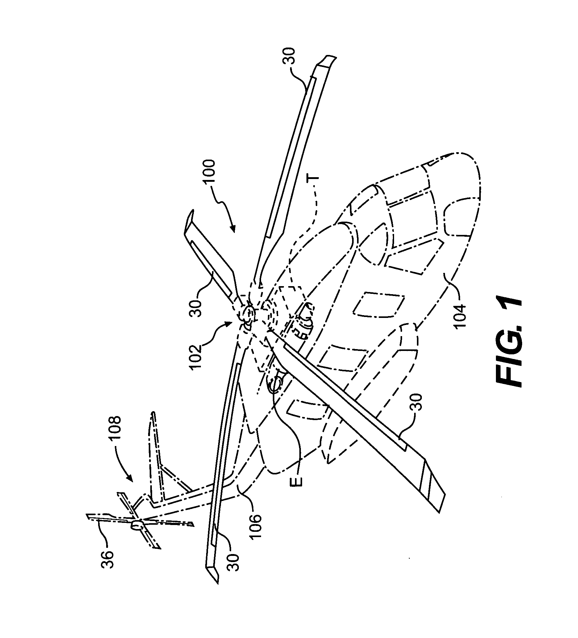
[0024]FIG. 1 schematically illustrates a rotary-wing aircraft 100 having a main rotor system 102 with rotor blade heater elements 30. The aircraft 100 includes an airframe 104 having an extending tail 106 on which mounts an antitorque tail rotor system 108. The main rotor assembly 102 is driven through a transmission (illustrated schematically at T) by one or more engines E. Although a particular helicopter configuration is illustrated in the disclosed embodiment, other machines such as turbo-props, tilt-rotor, and tilt-wing aircraft will also benefit from the present invention.

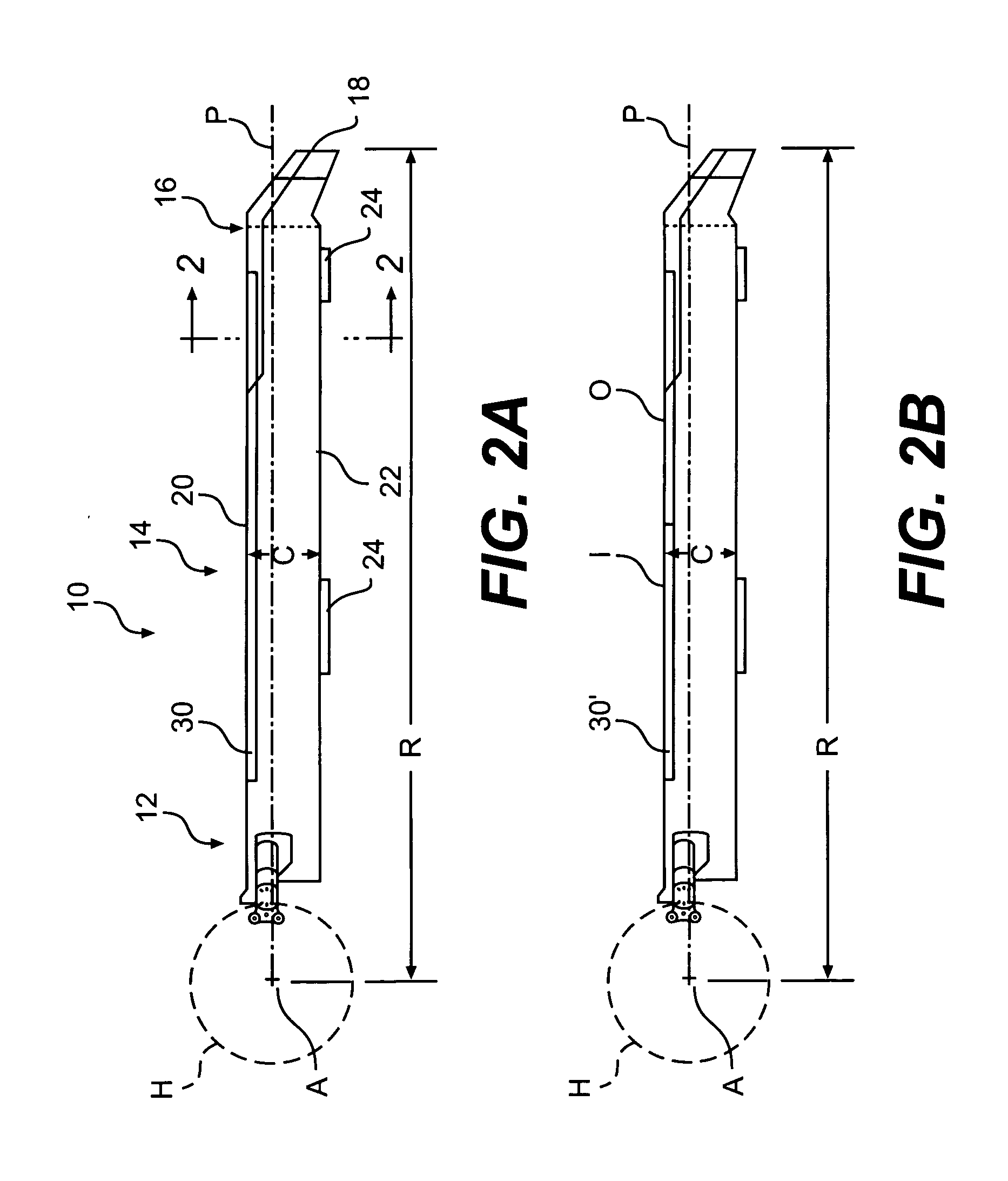
[0025]FIG. 2 schematically illustrates an exemplary main rotor blade assembly 10 mounted to a rotor hub assembly H (illustrated schematically) of the main rotor assembly 102 for rotation about an axis of rotation A. The main rotor blade assembly 10 includes an inboard section 12, an intermediate section 14, and an outboard section 16. The inboard, intermediate, and outboard sections 12, 14, 16 define the spa...


PUM


Abstract

A deicing system includes dual deice system components to provide a redundant deice system. Each redundant portion of the system generally includes a controller, an air data computer, an ice rate controller, and an ice rate probe. The controller communicating a heating cycle which defines a multiple of electric pulse trains to sequentially provides power to a multiple of heating elements in a designated blade set. Each electric pulse train is defined by an element on-time, a null time between the element on-time for this element and the next element, and an off-time between repetition of the heating cycle for the first heater element. The element on-time is a function of outside air temperature (OAT). The off-time is a function of liquid water content. The tail rotor heating cycle is a more straightforward version of the main rotor heating cycle as each of the tail rotor blade are activated simultaneously and there is only a single heating element on each tail rotor blade.

Description

BACKGROUND OF THE INVENTION [0001] The present invention relates to an aircraft deicing system, and more particularly to a dual primary deicing system for a rotor system of a rotary-wing aircraft. [0002] Rotary-wing aircraft may encounter atmospheric conditions that cause the formation of ice on rotor blades and other surfaces of the aircraft. Accumulated ice, if not removed, can add weight to the aircraft and may alter the airfoil configuration causing undesirable flying characteristics. [0003] One approach to ice management that has been used is thermal deicing. In thermal deicing, the leading edge portions of the rotor blades are heated to loosen accumulated ice. The loosened ice is then removed from the structural members by centrifugal forces and the airstream passing over the leading edge. [0004] In one form of thermal deicing, heating is accomplished by electrothermal heating elements over or within the leading edges of the airfoils. Electrical energy for the electrothermal h...

Claims


Application Information

Patent Timeline
IPC IPC(8): B64D15/00
CPCB64C27/04B64D15/14H05B1/0236B64D15/12B64D15/22
Inventor HOULIHAN, MICHAELFLEMMING, ROBERT J. JR.DANIELE, ANTONIO G.BUDD, TIMOTHY R.EISENHAUER, MARK P.
Owner SIKORSKY AIRCRAFT CORP
Why Eureka
Try Eureka