Lifting body tuned for passive re-entry

a technology for lifting bodies and re-entry vehicles, applied in the field of re-entry vehicles, can solve the problems of significant control problems, significant friction, drag and other aerodynamic forces, and generate tremendous heat, and achieve substantial cross-range and/or down-range descent path control, reduce acceleration, and reduce the effect of propellant requirements and risks to equipment and missions

Inactive Publication Date: 2006-10-12
LOCKHEED MARTIN CORP
View PDF22 Cites 15 Cited by
  • Summary
  • Abstract
  • Description
  • Claims
  • Application Information

AI Technical Summary

Benefits of technology

[0008] The present invention is directed to a re-entry vehicle and associated methodology that satisfies practical constraints relating to re-entry safety while allowing for lifting body functionality and associated advantages relating to descent path control and load reduction. The re-entry vehicle of the present invention has a configuration that allows for passive re-entry such that, in the case of manned flight, applicable safety standards can be satisfied without compromises to accommodate an escape pod. Even in the case of unmanned flight, propellant requirements and risks to equipment and missions can be significantly reduced in relation to controlled re-entry. Moreover, the invention allows for lifting body performance, for example, in the lower atmosphere, so as to enable substantial cross-range and / or down-range descent path control and reduced accelerations. High L / D ratios and active aerodynamic control can be accommodated so as to enable runway landings.
[0015] The present invention thus relates to turning a baseline design for a lifting body re-entry vehicle, or establishing an initial design, to more closely satisfy this equation, thereby reducing or substantially eliminating the need for active re-entry stability control. This equation, surprisingly, can be balanced for high performance vehicle configurations by careful aerodynamic tuning. Similarly, such tuning to more nearly satisfy this equation can reduce attitude control and propellant required during re-entry.
[0019] According to a still further aspect of the present invention, a high lift vehicle is provided that is capable of at least one degree of passive re-entry control. The vehicle includes internal structure defining a payload compartment and exterior structure defining a lifting body wherein, for a given angle of attack relative to a wind vector, the external structure provide an L / D ratio of at least about 0.6. In addition, for specified initial conditions regarding re-entry, the vehicle is configured in a manner that enables passive control with respect to at least one of a pitch, a roll and a yaw axis such that a status with respect to that axis is maintained within defined limits throughout a portion of a descent path substantially free from use of thrusters for angular stability control with respect to that axis. For example, the vehicle may allow for fully passive re-entry or for single axis active control, e.g., active roll control only. The high lift configuration allows for substantial descent path control and possible controlled, runway landings.

Problems solved by technology

One of the most challenging aspects of space flight is atmospheric re-entry, i.e., penetration of the Earth's outer atmosphere and descent to the Earth's surface.
Upon re-entry, the re-entry vehicle, generally moving at a near-orbital velocity, meets the outer atmosphere resulting in substantial friction, drag and other aerodynamic forces.
These forces generate tremendous heat and entail significant control issues.
Failure to protect against the heat of re-entry or to adequately address control issues can result in catastrophic failure.
In particular, the acceleration that can be tolerated by crew members is limited.
However, it is sometimes desired to utilize a lifting body for re-entry.
Today, the shuttle fleet remains grounded in the aftermath of the Columbia disaster.
That disaster looms large in the planning for future space flight, especially manned space flight.
Given that escape pod functionality imposes significant constraints on vehicle design and payload, some believe that a return to capsule-only re-entry for manned space flight is inevitable; that is, that capsule only re-entry is being practically if not explicitly required.

Method used


Image

  • Lifting body tuned for passive re-entry
  • Lifting body tuned for passive re-entry
  • Lifting body tuned for passive re-entry

Examples


Embodiment Construction

[0031] In the following description, the invention is set forth with respect to specific re-entry vehicle configurations that provide for passive re-entry control for a lifting body re-entry vehicle. It will be appreciated that these particular configurations were achieved by taking a proposed vehicle design, developed based on a variety of mission considerations, and tuning the design, in accordance with certain principles described below, to achieve the desired level of passive re-entry control. Accordingly, it will be appreciated that other designs may be developed in accordance with the present invention. The following description, therefore, should be understood as exemplifying the invention and not by way of limitation.

[0032] The following description begins by setting forth the principles which have been found, surprisingly, to allow for passive re-entry control by a high performance re-entry vehicle. Thereafter, the description includes a generalized discussion of a re-entr...


PUM


Abstract

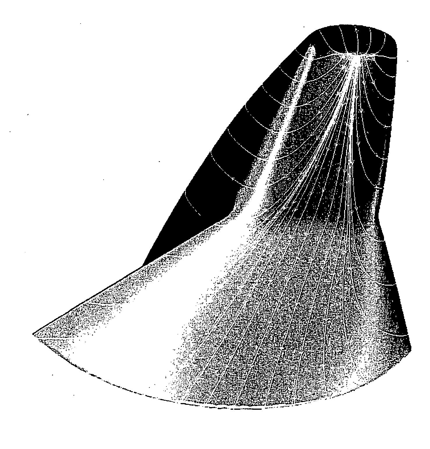
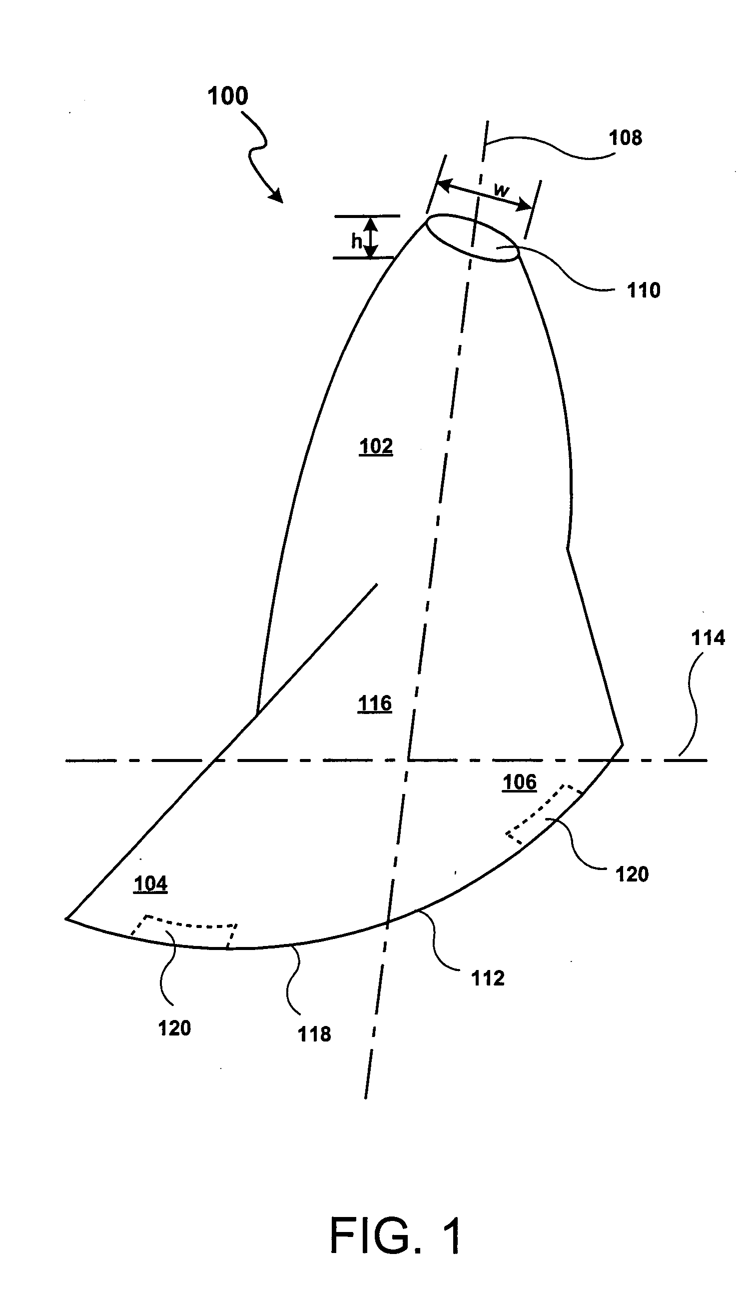
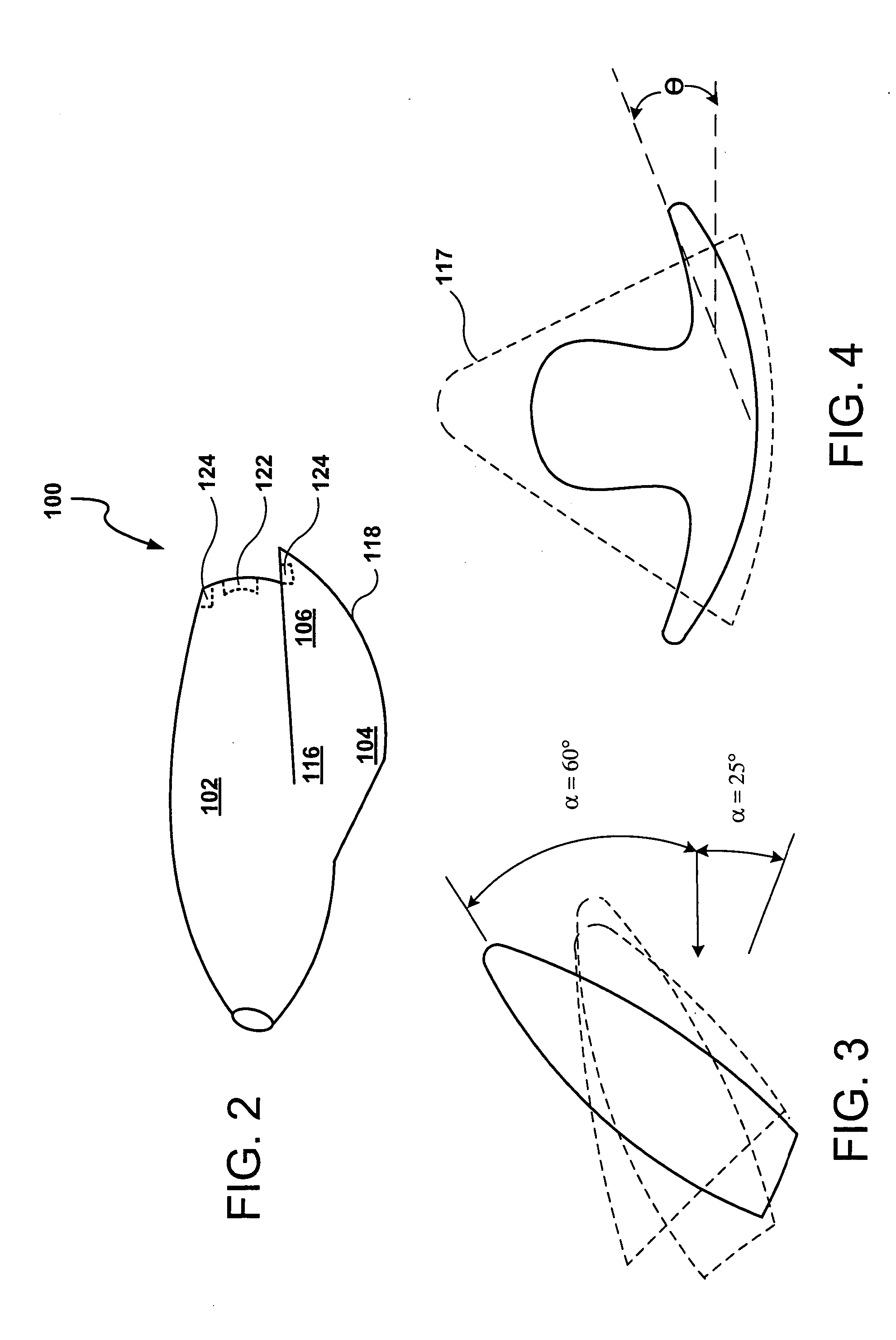
A high performance (high L / D ratio) launch vehicle is tuned for passive or limited control re-entry. In one embodiment, the re-entry vehicle (100) includes a fuselage portion (102) and wing portions (104 and 106) extending from opposite sides thereof. Various vehicle configuration parameters are tuned to allow for passive or limited control re-entry. In particular, the swept wings have a dihedral configuration and the nose of the vehicle (100) is widened. In operation, the vehicle (100) penetrates the outer atmosphere at a high angle of attack and transitions to an aerodynamic angle of attack for substantial cross range and down range control within the lower atmosphere. The vehicle (100) thereby provides for enhanced re-entry safety while reducing propellant requirements, reducing loads and meeting human rating requirements.

Description

FIELD OF THE INVENTION [0001] The present invention relates generally to re-entry vehicles and, in particular, to a vehicle adapted for passive re-entry, like a capsule, and aerodynamically controlled gliding or powered flight, like an aerospace plane. BACKGROUND OF THE INVENTION [0002] One of the most challenging aspects of space flight is atmospheric re-entry, i.e., penetration of the Earth's outer atmosphere and descent to the Earth's surface. Upon re-entry, the re-entry vehicle, generally moving at a near-orbital velocity, meets the outer atmosphere resulting in substantial friction, drag and other aerodynamic forces. These forces generate tremendous heat and entail significant control issues. Failure to protect against the heat of re-entry or to adequately address control issues can result in catastrophic failure. The loss of the U.S. Space Shuttle Columbia provides a grim illustration of the potential consequences in this regard. [0003] Protection against the heat of re-entry ...

Claims


Application Information

Patent Timeline
Patent Type & Authority Applications(United States)
IPC IPC(8): B64G1/00
CPCB64G1/62
Inventor GULICK, DOUGLAS S.BOMBA, JOSEPH V.
Owner LOCKHEED MARTIN CORP
Why Eureka
Try Eureka