In-plane switching mode liquid crystal display device

Active Publication Date: 2006-10-12
LG DISPLAY CO LTD
View PDF2 Cites 32 Cited by
  • Summary
  • Abstract
  • Description
  • Claims
  • Application Information

AI Technical Summary

Benefits of technology

[0020] An object of the present invention is to provide an In-Plane Switching (IPS) mode LCD device having improved transmittance.
[0021]

Problems solved by technology

Despite various technical developments in the LCD technology, research in enhancing the picture quality of the LCD device has been, in some respects, lacking as compared to other features of the LCD device.
This is commonly referred to as a Twisted Nematic (TN) mode LCD device, which has a problem of a narrow viewing angle.
However, increasing the width of the black matrix layer 41 will increase aperture ratio loss.
If the data line is formed at a predetermined interval from the outermost common electrode, crosstalk is generated in the space between

Method used


Image

  • In-plane switching mode liquid crystal display device
  • In-plane switching mode liquid crystal display device
  • In-plane switching mode liquid crystal display device

Examples


Embodiment Construction

[0040] Reference will now be made in detail to the preferred exemplary embodiments of the present invention, examples of which are illustrated in the accompanying drawings.

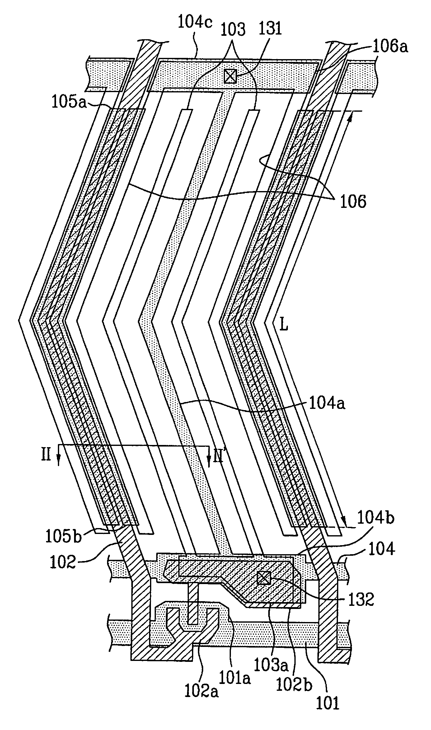
[0041]FIG. 5 is a plan view of an exemplary IPS mode LCD device according to the present invention and FIG. 6 is a cross sectional view along II-II′ of FIG. 5 according to the present invention. As shown in FIGS. 5 and 6, the IPS mode LCD device includes first and second substrates 100 and 110 facing each other, and a liquid crystal layer 120 formed between the first and second substrates 100 and 110. The first substrate 100 includes a plurality of gate and data lines 101 and 102 crossing each other to define pixel regions, a plurality of thin film transistors TFT formed adjacent to crossings of the gate and data lines 101 and 102, first and second electrode patterns 105a and 105b, a common line 104, common electrodes 106 and 104a, and a pixel electrode 103. The first and second electrode patterns 105a and 105b a...


PUM


Abstract

An IPS mode LCD device includes first and second substrates facing each other, gate and data lines on the first substrate and crossing each other to define a plurality of unit pixel regions, first and second electrode patterns formed in an island shape at a pre-determined interval therebetween and overlapped with sides of the data line, a plurality of common electrodes formed in the unit pixel regions, each of the common electrodes having outermost common electrodes partially overlapped with the first and second electrode patterns, a pixel electrode alternately provided with the common electrodes within the pixel unit region, and a liquid crystal layer formed between the first and second substrates.

Description

The present application claims the benefit of the Korean Patent Application No. P2005-29936, filed on Apr. 11, 2005 in Korea, which is hereby incorporated by reference. BACKGROUND OF THE INVENTION [0001] 1. Field of the Invention [0002] The present invention relates to a method for manufacturing a liquid crystal display (LCD) device, and more particularly, to an In-Plane Switching (IPS) mode LCD device having improved transmittance and viewing angle. [0003] 2. Discussion of the Related Art [0004] Demands for various display devices have increased with development of an information based society. Accordingly, many efforts have been made to research and develop various flat display devices, such as liquid crystal display (LCD) devices, plasma display panel (PDP) devices, electroluminescent display (ELD) devices, and vacuum fluorescent display (VFD) devices. Some versions of flat display devices have already been implemented into displays for various equipment. [0005] Among the various...

Claims


Application Information

Patent Timeline
IPC IPC(8): G02F1/1343
CPCG02F1/134363G02F2001/136218G02F2001/13606G02F1/13606G02F1/136218G02F1/1343
Inventor SON, HYEON HO
Owner LG DISPLAY CO LTD
Why Eureka
Try Eureka