Displacement sensor

a displacement sensor and sensor technology, applied in the field of optical sensors, can solve the problems of undesirable noise into the resulting sensor output, affecting the actual implementation of displacement sensors in portable devices such as hearing aids, and affecting the accuracy of displacement sensors, so as to reduce the power operation and reduce the noise of signal

Inactive Publication Date: 2006-10-12
GEORGIA TECH RES CORP +1
View PDF59 Cites 52 Cited by
  • Summary
  • Abstract
  • Description
  • Claims
  • Application Information

AI Technical Summary

Benefits of technology

[0012] Optical sensors, and methods for operating optical sensors, are disclosed. The sensors and methods provide for reduced power operation and / or reduced signal noise in comparison to conventional sensors.

Problems solved by technology

However, actual implementation of the displacement sensors in portable devices, such as hearing aids, has been hampered by the power use of these sensors.
Although semiconductor laser diodes are known to be more power efficient in comparison to, for example, a stabilized laser such as a Helium-Neon (HeNe) laser, semiconductor lasers have not been favored in high-sensitivity optical detection devices such as displacement sensors because of their thermal instability, low coherence length, and high laser intensity noise.
Additionally, the photo-detectors used for measuring the reflected and diffracted light from the grating and reflector can also introduce undesirable noise into the resulting sensor output.

Method used


Image

  • Displacement sensor
  • Displacement sensor
  • Displacement sensor

Examples


Embodiment Construction

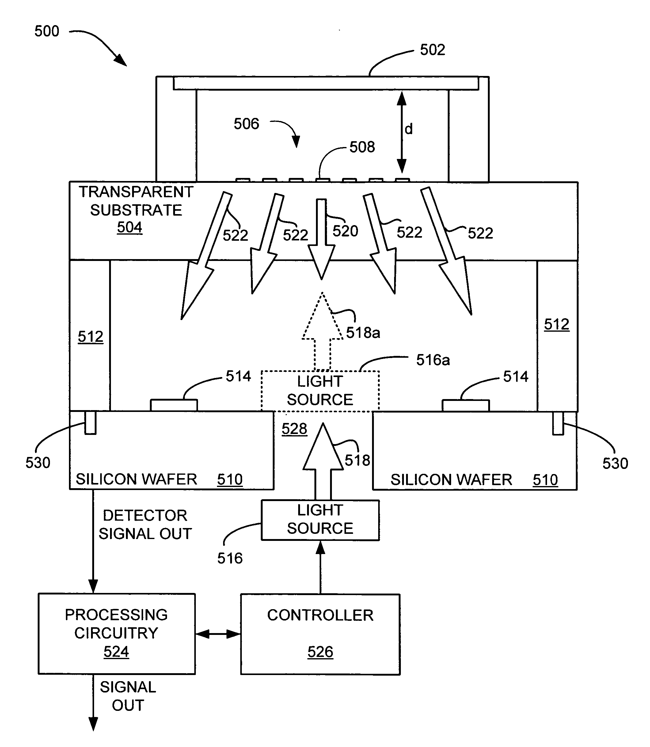
[0033] Embodiments of devices and associated methods for displacement sensing using optical interferometric techniques are disclosed. More specifically, the present disclosure relates to miniature devices for accurately measuring the movement of a mechanical device, such as a flexible membrane that is affected by a number of possible external excitations, such as acoustic pressure, a chemical reaction, acceleration, vibration, and / or other physical forces.

[0034] According to the present disclosure, such devices and methods can use a modulated emission of light for reducing power consumption of an associated light source and / or for reducing associated signal noise associated with conventional optical sensors. The modulated emission of light, which may also be referred to as a modulated light emission, can be varied at a modulation frequency. For example, according to one embodiment, the modulated emission of light can be provided by a pulsed light source, which could comprise emitti...


PUM


Abstract

Optical sensors, and methods for operating optical sensors, are disclosed. One such sensor may include: a reflector positioned a distance from a reflective diffraction grating and a light source for providing light. A first portion of the light can be reflected from the reflective diffraction grating and a second portion of the light passes through the grating to the reflector and is reflected back through the diffraction grating. The sensor may further include a detector for sensing an intensity of light in an interference pattern formed by the first portion of the light reflected from the diffraction grating and the second portion of the light reflected from the reflector. The sensor includes a controller configured to modulate an emission of the light.

Description

CROSS-REFERENCE TO RELATED APPLICATIONS [0001] This application claims priority to and benefit of U.S. Provisional Patent Application entitled “OPTICAL INTERFEROMETRIC SENSORS WITH LOW POWER CONSUMPTION AND LOW NOISE,” assigned Ser. No. 60 / 634,324, and filed on Dec. 8, 2004, which is incorporated by reference in its entirety.STATEMENT REGARDING FEDERALLY SPONSORED RESEARCH OR DEVELOPMENT [0002] The U.S. Government may have a paid-up license in this invention and the right in limited circumstances to require the patent owner to license to others on reasonable terms as provided for by the terms of Contract No. DAAD19-00-1-0174, awarded by DARPA through the Army Research Laboratory.BACKGROUND [0003] 1. Technical Field [0004] The present disclosure generally relates to optical sensors, and more specifically, to interferometric optical sensors using a modulated emission of light for displacement measurement. [0005] 2. Description of the Related Art [0006] Hearing aids, among a number of ...

Claims


Application Information

Patent Timeline
Patent Type & Authority Applications(United States)
IPC IPC(8): H01S3/08
CPCG01D5/38G01D5/285B33Y80/00H04R23/008
Inventor DEGERTEKIN, FAHRETTIN LEVENTLEE, WOOKHALL, NEAL ALLEN
Owner GEORGIA TECH RES CORP
Why Eureka
Try Eureka