Supercavitating medical probe and method of use

a medical probe and supercavitation technology, applied in the field of instruments and techniques, can solve the problems of sudden rise in ambient pressure, strong local shockwaves, unintended and undesirable cavitation phenomena, etc., and achieve the effect of reducing viscous drag and high straight line velocity

Active Publication Date: 2006-10-12
RELIGN CORP
View PDF17 Cites 15 Cited by
  • Summary
  • Abstract
  • Description
  • Claims
  • Application Information

AI Technical Summary

Benefits of technology

[0012] In one example, the supercavitation phenomenon is used to allow objects to travel under water at high speed. The Russian Shkval torpedoes may be the only publicly known practical application of supercavitation technology. The supercavitating Shkval torpedo is believed to rotate at high speed and more importantly has a rocket-powered high straight line velocity. The torpedo body reportedly has faceted cavitators on its nose to induce a cavitation envelope that will extend to cover the entire body when it reaches speeds in excess of about 150-200 km / h under water. Thereafter, the torpedo is no longer moving through water, but through a supercavity akin to air. The sustainable envelope or supercavity results in water wetting very little of the body's surface, thereby drastically reducing viscous drag. The drag reduction reportedly allows for torpedo speeds in excess of 500 km / h.

Problems solved by technology

In conventional hydrodynamic terms, cavitation is an unintended and undesirable phenomenon.
The regions of cavitation are transient as the cavities implode when the fluid flow velocities subside resulting in a sudden rise in ambient pressure.
The collapse of the cavities can cause very strong local shockwaves in the fluid, which may be audible and may damage adjacent structures.

Method used


Image

  • Supercavitating medical probe and method of use
  • Supercavitating medical probe and method of use
  • Supercavitating medical probe and method of use

Examples


Embodiment Construction

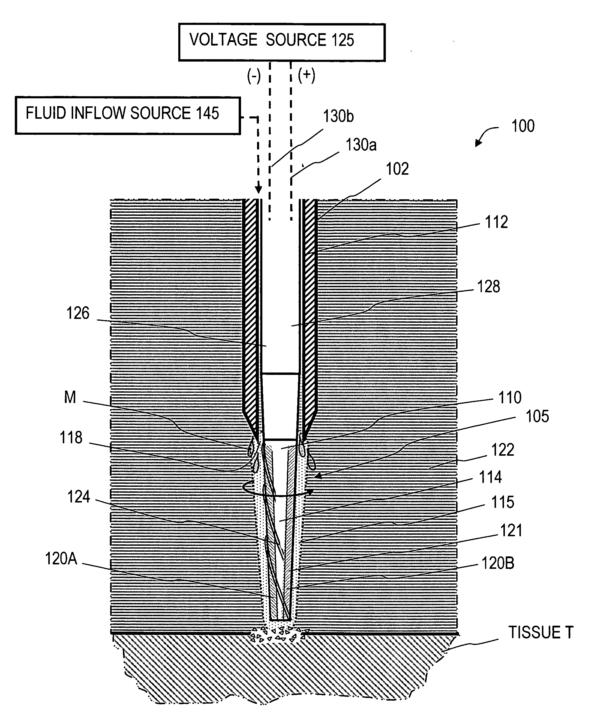
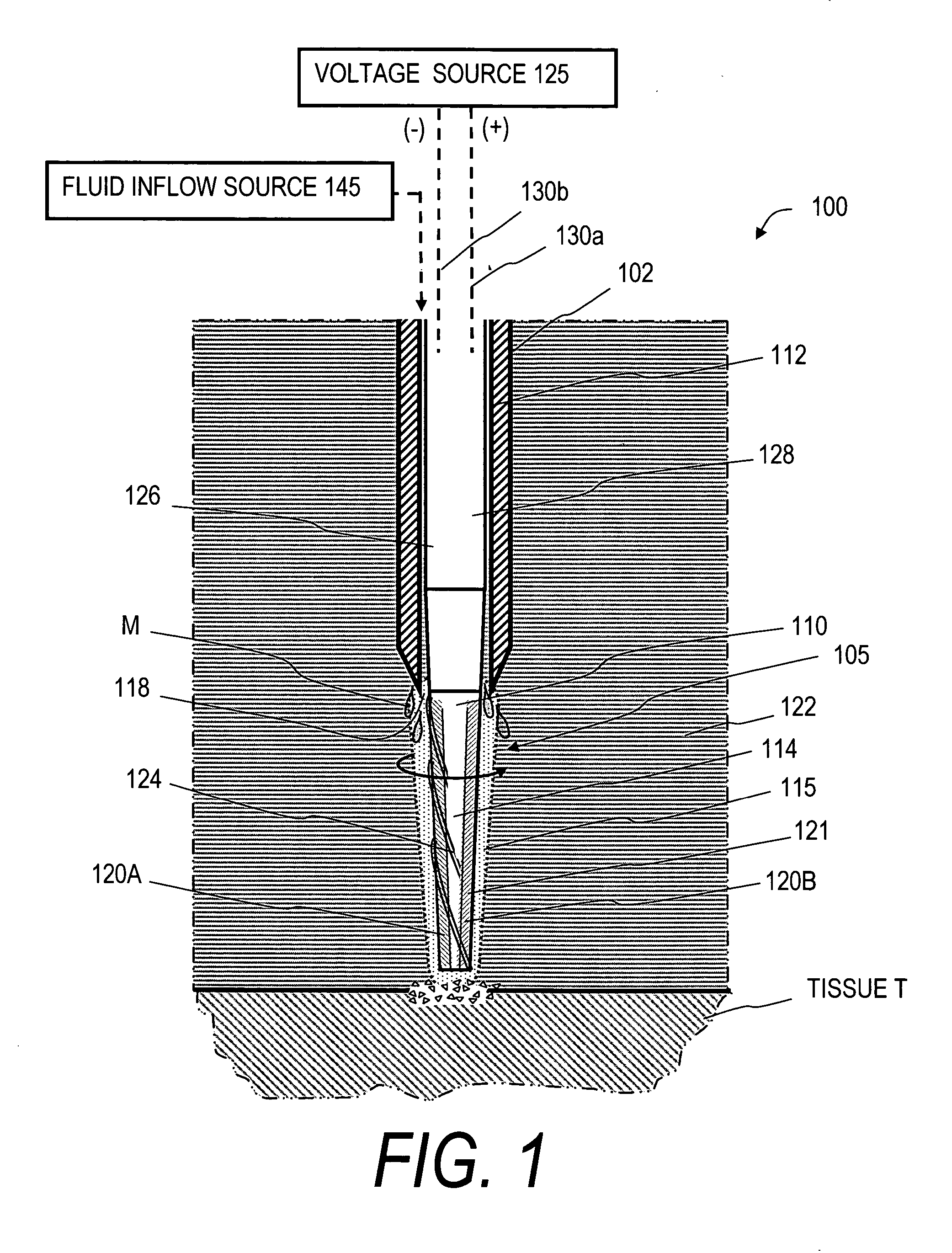
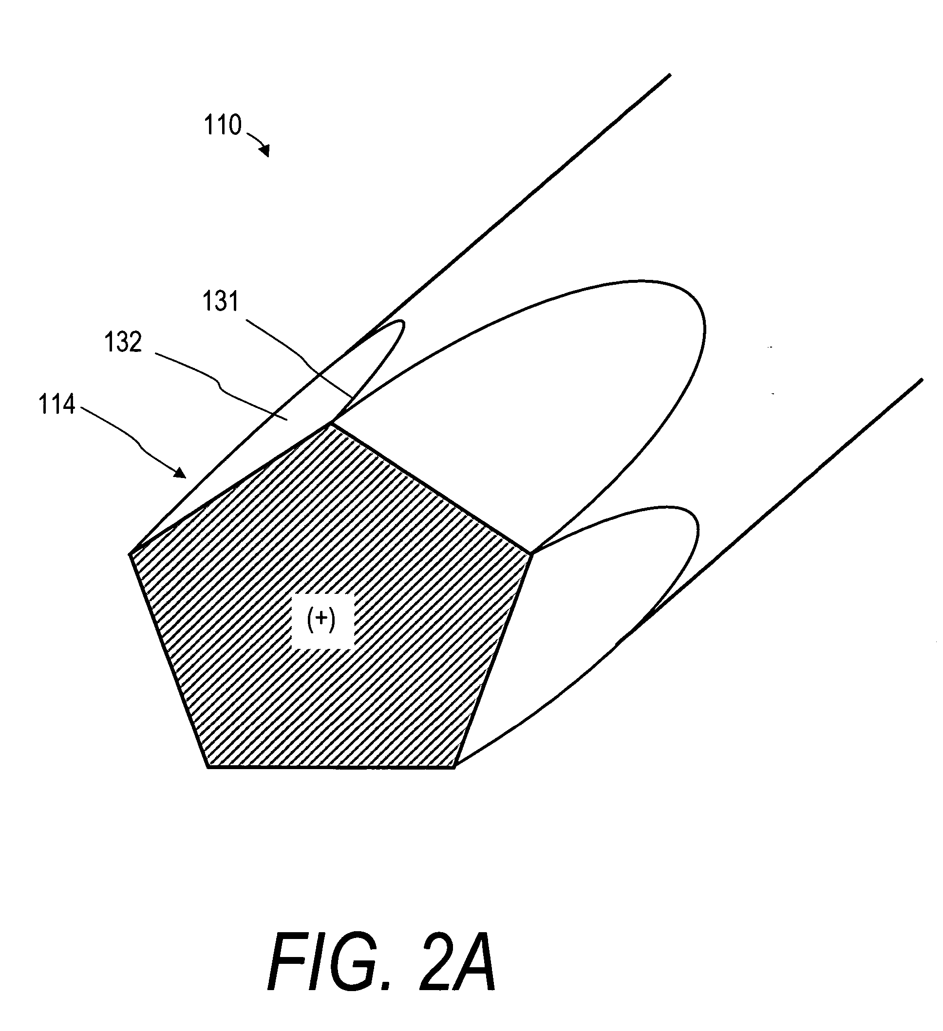
[0030]FIG. 1 illustrates an instrument system that comprises a medical probe 100 with a distal portion shown in FIG. 1 that is configured for creating cavitation and supercavitation about an actuatable or moveable surface for controlling the application of electrosurgical energy to tissue. In FIG. 1, an elongated shaft or sleeve member 102 carries an actuatable, moveable working end indicated at 105. In the embodiment of FIG. 1, the actuatable working end 105 comprises an elongated rotatable member 110 that extends through bore 112 in the shaft member 102 and is operatively coupled to a motor drive described further below. The rotatable member 110 and working end 105 is rotatable at a very high speed wherein the working surface 114 creates a cavity or supercavity 115 that can substantially envelope the working end. In the embodiment of FIG. 1, it can be seen that the actuatable working end 105 is exposed to extend outwardly from open termination 118 of bore 112, but the working end ...


PUM


Abstract

An electrosurgical working end that utilizes supercavitation phenomenon for controlled application of electrosurgical energy to tissue. In one preferred method of the invention, the system utilizes an electrosurgical surface that is rotatable in a liquid substance at very high surface velocities capable of localized lowering of the pressure of the substance below its saturated vapor pressure to cause supercavitation, and contemporaneously applying electrical energy from the electrosurgical surface across the cavity to ablate adjacent tissue. The system creates supercavitation with surface velocities of greater than about 70 m / sec in a liquid substance by means of high speed rotation and optionally ultrasound actuation.

Description

CROSS-REFERENCE TO RELATED APPLICATIONS [0001] This application claims benefit of Provisional U.S. Patent Application Ser. No. 60 / 636,352 filed Dec. 14, 2004 titled Supercavitating Electrosurgical Device and Method of Use, and also claims benefit of Provisional U.S. Patent Application Ser. No. 60 / 636,355 filed Dec. 14, 2004 titled Supercavitating Medical Probe and Method of Use, both of which are incorporated herein and made a part of the specification.BACKGROUND OF THE INVENTION [0002] 1. Field of the Invention [0003] The invention is related to instruments and techniques for controlled application of energy to tissue, and more particularly relates to supercavitating surfaces and electrosurgical surfaces for ablating tissue layers, for ablating holes in soft tissue and for ablating occlusive materials, calculi and the like. [0004] 2. Description of the Related Art [0005] Various electromagnetic and acoustic energy delivery sources have been investigated for surgical tissue ablation...

Claims


Application Information

Patent Timeline
Patent Type & Authority Applications(United States)
IPC IPC(8): A61B18/14
CPCA61B18/148A61B2017/22014A61B2018/00208A61F9/0079A61B2218/002A61B2218/007A61B2018/1861A61B2017/320069A61N7/02A61N7/022
Inventor SHADDUCK, JOHN H.
Owner RELIGN CORP
Why Eureka
Try Eureka