

Multi-core model simulator
a model simulator and multi-core technology, applied in the field of multi-core model simulators, can solve the problems of inability to achieve sufficient simulation speed, inability to handle multi-cores, and difficulty in the development of high-speed software/hardware cooperative simulators
- Summary
- Abstract
- Description
- Claims
- Application Information
AI Technical Summary
Benefits of technology
Problems solved by technology
Method used
Image

Examples
first embodiment
[0023]FIG. 9 is a block diagram showing a hardware configuration example of a multiprocessor core model simulator 900 according to a first embodiment of the present invention. The simulator 900 has, for example, two processor (CPU) cores 901 and 902, a memory 903 and a chip set 904. The simulator 900 of this embodiment uses a computer with the multiprocessor cores 901 and 902 (for example, a computer of two-processor configuration of XEON of an INTEL CUP, or the like). Note that a computer which has only one processor, but logically has two-processor configuration, such as Pentium (trade name) 4 is included.
[0024]FIG. 10 is a diagram for explaining a multiprocessor core model according to this embodiment. The multiprocessor core model is realized by the hardware configuration in FIG. 9. Processor core models PE0 and PE1 correspond to the processor cores 901 and 902 in FIG. 9. However, to which of the processor cores 901 and 902 each of the processor core models PE0 and PE1 is assig...
second embodiment
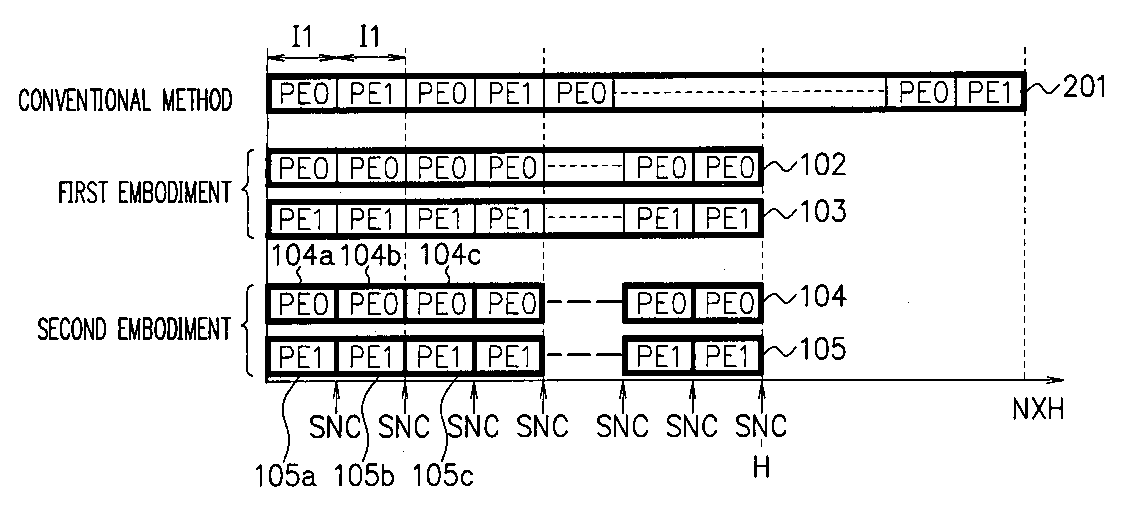
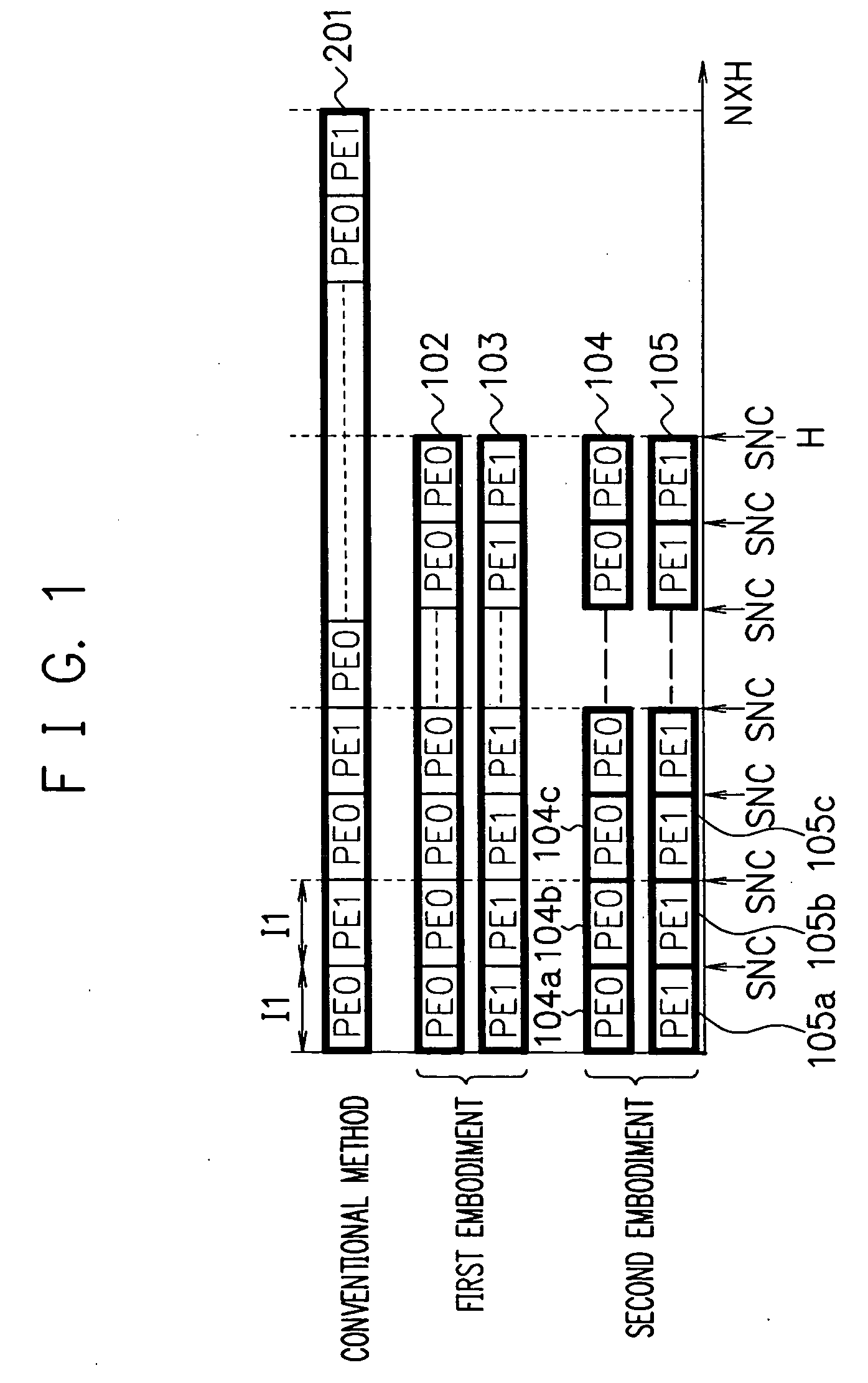
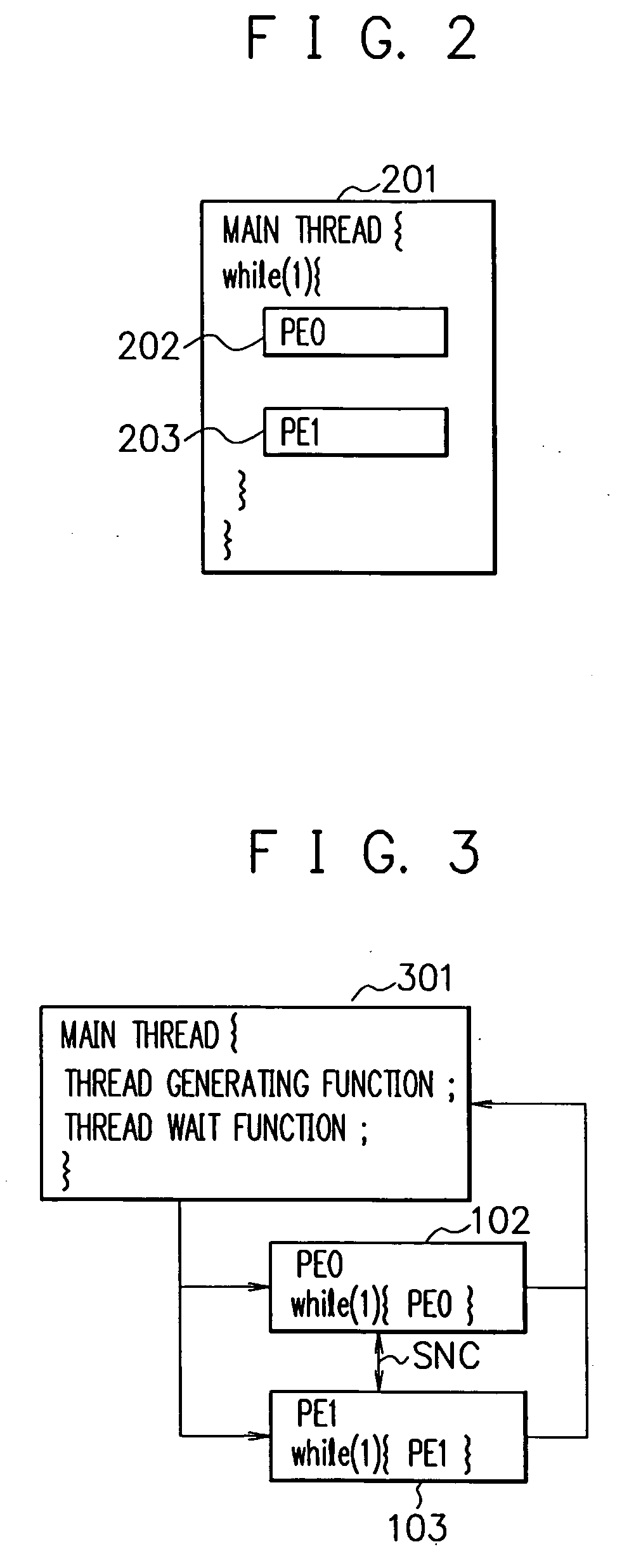
[0037]FIG. 4 is a diagram showing an example of a main thread 401 of a multiprocessor core model simulator according to a second embodiment of the present invention. The main thread 401 has a thread generating function for generating each thread of thread groups 104 and 105, and a thread wait function for waiting for termination of each thread of the thread groups 104 and 105, and performs loop processing of these functions. As shown in FIGS. 1 and 4, the thread group 104 includes the threads executed by the processor core model PE0, and has threads 104a, 104b, 104c . . . which are divided every predetermined number I1 of execution instructions. The thread group 105 includes threads executed by the processor core model PE1, and has threads 105a, 105b, 105c, . . . which are divided every predetermined number I1 of execution instructions. Note that in FIG. 1, the thick frame represents one thread. The processor core models PE0 and PE1 respectively execute a plurality of threads of the...
third embodiment
[0043]FIG. 6 is a diagram for explaining a multicore model simulator according to a third embodiment of the present invention. In this embodiment, as in the second embodiment (FIG. 1), the processor core model PE0 executes the thread group 104, the processor core model PE1 executes the thread group 105, and further, a hardware model HW executes a thread group 601. The thread groups 104, 105 and 601 are executed in parallel. The synchronization method is the same as that in the second embodiment. The hardware model HW is the model which is assigned to the processor core to simulate a hardware model. For example, in FIG. 9, another processor core is provided in addition to the processor cores 901 and 902. The hardware model HW is a core model other than the processor core models, and is a model for simulating a hardware model of, for example, image processing, audio processing, reconfiguration processing, timer, bus block or the like.
[0044] This embodiment shows a simulator example o...
PUM
 Abstract
Description
Claims
Application Information