Method and apparatus for satellite positioning of earth-moving equipment

a satellite positioning and earth-moving equipment technology, applied in the field of positioning and, can solve the problems of equipment adding substantially to the overall cost of the system, reducing limiting the system in certain respects, so as to reduce the overall positional accuracy of the leading edge of the bucket, accurately mount and calibrate

Active Publication Date: 2006-10-19
TOPCON POSITIONING SYST INC
View PDF41 Cites 31 Cited by
  • Summary
  • Abstract
  • Description
  • Claims
  • Application Information

AI Technical Summary

Benefits of technology

[0008] While earthmoving machines, such as the aforementioned excavators, using satellite positioning systems are advantageous in many applications, the present inventor has recognized that these systems are limited in certain regards. For example, while such systems are more accurate than prior, manual methods of excavation, they require several measurements by angle sensors in addition to the measurements by the satellite positioning system. Each of the measurements by these additional sensors adds error, thus reducing the overall positional accuracy of the leading edge of the bucket. Additionally, multiple angle sensors and associated electronics equipment are required to calculate the necessary geometric positional data. Such equipment adds substantially to the overall cost of the system. Finally, additional work is required to accurately mount and calibrate each of the sensors.

Problems solved by technology

While earthmoving machines, such as the aforementioned excavators, using satellite positioning systems are advantageous in many applications, the present inventor has recognized that these systems are limited in certain regards.
Each of the measurements by these additional sensors adds error, thus reducing the overall positional accuracy of the leading edge of the bucket.
Such equipment adds substantially to the overall cost of the system.

Method used


Image

  • Method and apparatus for satellite positioning of earth-moving equipment
  • Method and apparatus for satellite positioning of earth-moving equipment
  • Method and apparatus for satellite positioning of earth-moving equipment

Examples


Embodiment Construction

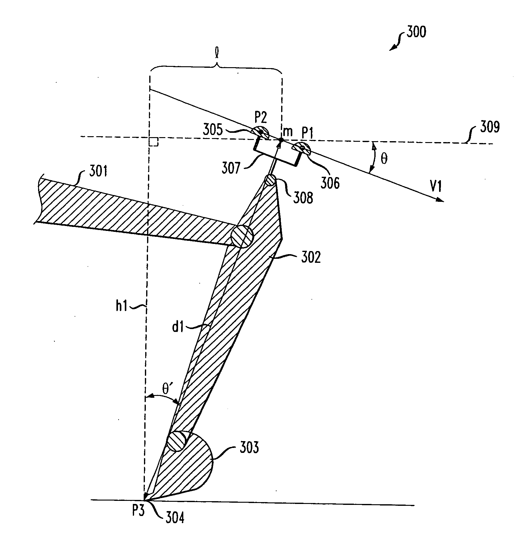
[0019]FIG. 3 shows a boom, stick and bucket assembly of an illustrative excavator in accordance with the principles of the present invention. The boom and stick are also referred to herein as “load-bearing arms”. Specifically, referring to FIG. 3, boom 301 is connected to stick 302 which is, in turn, attached to bucket 303, as discussed above. However, unlike the previously discussed excavators that utilized a satellite positioning system to assist in the control of the machine, the antennas 305 and 306 are mounted on support structure 307 which is attached to stick 302 at illustrative point 308. One skilled in the art will recognize that antennas 305 and 306 may be positioned in many different configurations. For example, the antennas may each be mounted separately on the stick. Additionally, while the antennas are shown mounted longitudinally along the stick, one skilled in the art will recognize that other mounting configurations are possible.

[0020] In the illustrative excavator...


PUM


Abstract

A method and apparatus for using satellite positioning systems to more precisely locate the position of a portion of an attachment on an earthmoving machine is disclosed. More specifically, satellite positioning system antennas are mounted to an arm or other point relative to the arm of an illustrative excavator. A reference point relative to these antennas is used to determine the precise location of a portion of an attachment to the excavator, such as the prongs of a bucket. In one embodiment, an angle sensor or inclinometer is used to ascertain the position of the prongs when the bucket is scooped. In another embodiment, an angle sensor or inclinometer is used to measure the tilt of the body of the excavator, such as would occur when the excavator is resting on a sloped surface.

Description

BACKGROUND OF THE INVENTION [0001] The present invention relates generally to positioning and, and more particularly to the dynamic positioning of excavators. [0002] Various types of machines, referred to herein as earthmoving machines, have been developed to alter the topology or geography of terrain. FIG. 1 shows one such earthmoving machine, an excavator, which is well known in the art. As shown in FIG. 1, excavators such as excavator 100 typically have a main body 101 with a vehicle operator cab 102. Attached to the main body 101 is arm 103, commonly referred to as a “boom.” Boom 103 is, in turn, attached to a second arm 104, commonly referred to as a “stick.” Stick 104 may be adapted to hold different attachments. Here, stick 104 is attached, illustratively, to a bucket 105 for use in excavation / digging. Bucket 105 typically has prongs 106 attached to the leading edge of the bucket 105 that are used to break through ground and other materials to be excavated. Body 101 is attach...

Claims


Application Information

Patent Timeline
Patent Type & Authority Applications(United States)
IPC IPC(8): E02F5/02
CPCE02F3/437
Inventor MCCAIN, STEVEN DANIEL
Owner TOPCON POSITIONING SYST INC
Why Eureka
Try Eureka