
Air conditioner

a technology for air conditioners and fans, applied in the field of air conditioners, can solve the problems of difficult to prevent dew condensation, troublesome sealing, strange (complicate) shape, etc., and achieve the effect of reducing size and small siz

Inactive Publication Date: 2006-10-19
DENSO CORP
View PDF4 Cites 17 Cited by
  • Summary
  • Abstract
  • Description
  • Claims
  • Application Information

AI Technical Summary

Benefits of technology

[0009] In view of the above-described disadvantages, it is an object of the present invention to provide an air conditioner, in which a mounting performance of a heat-insulating seal member at a connection part between an evaporator-side connector and a piping-side connector is improved and dew condensation is substantially restricted.
[0013] Therefore, the connection part between the evaporator-side connector and the piping-side connector can be relatively small-sized. Moreover, because the heat-insulating seal member is arranged at the side of the piping group at the connection part between the evaporator-side connector and the piping-side connector, the heat-insulating seal member can be readily attached even when the space around the connection part is small.
[0014] Furthermore, the heat-insulating seal member covers the whole area between the surrounding wall member and the outer peripheral surfaces of the piping group, so that the heat insulation capacity can be substantially ensured. Thus, dew condensation can be substantially restricted, while the mounting performance of the heat-insulating seal member is improved.
[0016] Because the surrounding wall member extends to the vicinity of the piping group, the mounting of the heat-insulating seal member become further easy while the heat-insulation seal capacity can be further improved.
[0018] In this case, the heat-insulating seal member can be mounted from the outer side of the surrounding wall member and the piping group, so that the mounting thereof can be further readily performed.
[0020] Thus, the heat-insulating seal member can be arranged at the inner side of the surrounding wall member, to be size-reduced. Therefore, even when the space around the surrounding wall member is small, the heat-insulating seal member having a relative small size can be mounted. Accordingly, the mounting of the heat-insulating seal member can be readily performed.

Problems solved by technology

Thus, attachment of the seal member becomes troublesome.
Furthermore, it is difficult to prevent dew condensation by means of a substantial heat-insulating sealing, because the part covered by the seal member has a complex shape.
In the case where the periphery of the expansion valve is surrounded completely by the rib and covered by the seal member, the rib is to be provided with a greatly strange (complicate) shape, and the space for mounting becomes large.
Moreover, the seal member becomes relatively large.
Furthermore, when the rib has the complicate shape, a clearance is liable to generate at the attachment of the seal member.
Therefore, it is difficult to prevent dew condensation by means of a substantial heat-insulation sealing.
Therefore, when other equipment (e.g., servomotor and linkages for driving door means in casing) is mounted around the connection part outside the air conditioner casing, the space for mounting the seal member is difficultly provided and the mounting performance is worsened.

Method used


Image

  • Air conditioner
  • Air conditioner
  • Air conditioner

Examples


first embodiment

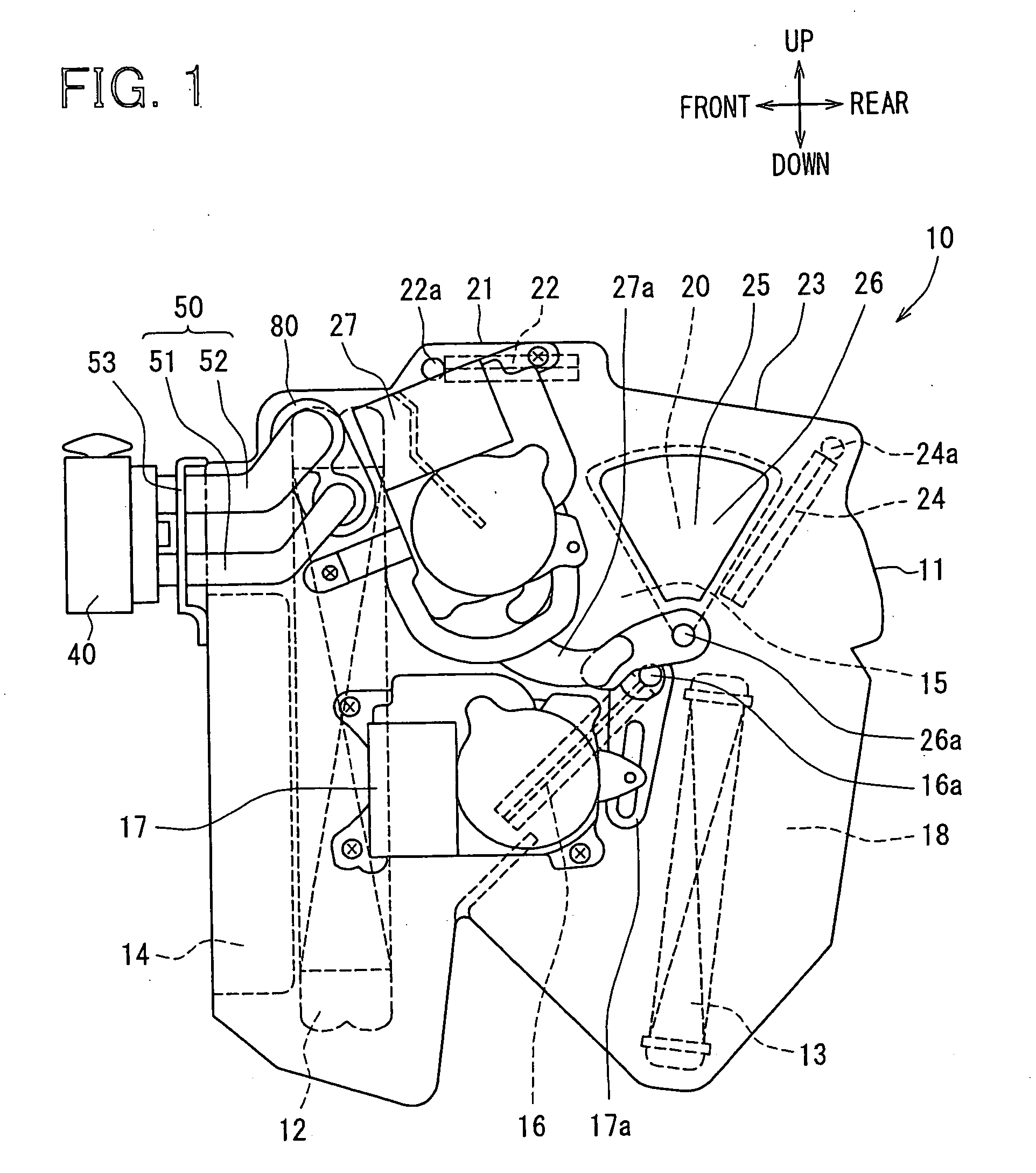
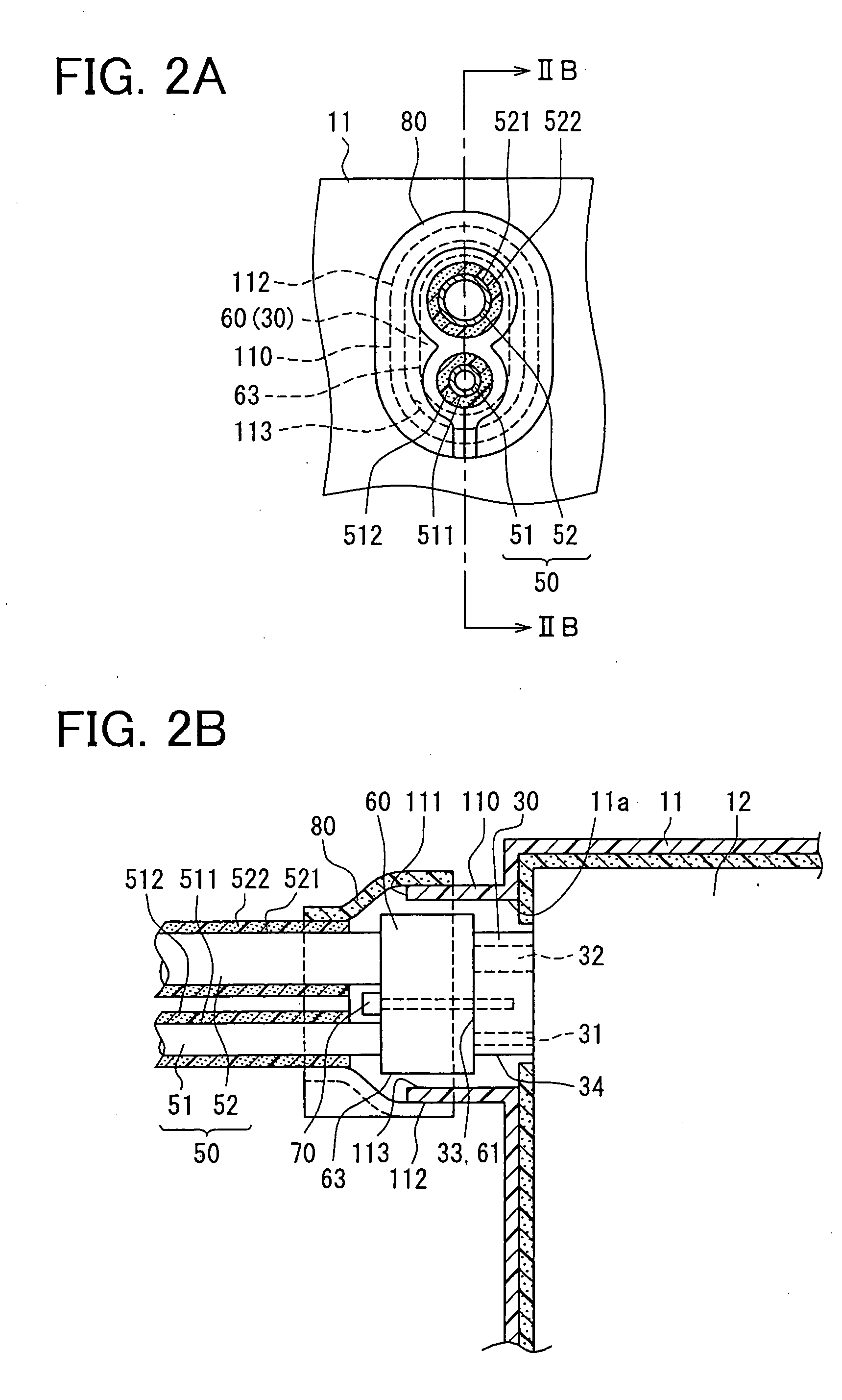
[0029] An air conditioner according to a first embodiment of the present invention will be described with reference to FIGS. 1-2B. The air conditioner can be suitably used for a vehicle, for example.

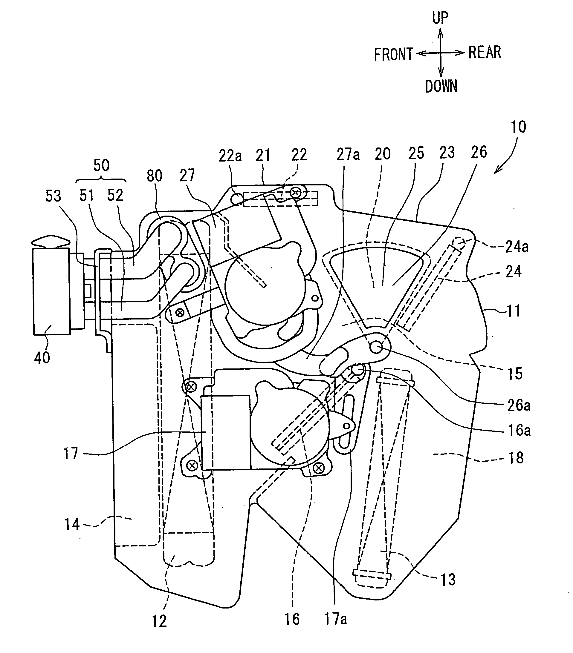
[0030] A ventilation system of the air conditioner for the vehicle is mainly divided into two parts, that is, an air conditioning component 10 (of indoor unit) shown in FIG. 1 and an air blower component (not shown). The air blower component is arranged offset to an assistant seat from a central portion below a dashboard in a passenger compartment of the vehicle, while the air conditioning component 10 is arranged substantially centrally in a vehicle left-right direction below the dashboard in the passenger compartment.

[0031] The air blower component, as well known, has an inside / outside air switching box for selectively introducing inside air (air in passenger compartment) and outside air (air outside passenger compartment), and an air blower which blows air introduced through the ins...

second embodiment

[0085] A second embodiment according to the present invention will be described with reference to FIGS. 3A and 3B. In this case, the seal packing 80 contacts a different part of the surrounding wall member 110 from that in the above-described first embodiment.

[0086] According to the second embodiment, as shown in FIGS. 3A and 3B, the heat-insulating seal member 80 (e.g., seal packing) is arranged to contact the inner peripheral surface 113 of the surrounding wall member 110 and the insulators 512 and 522 which are respectively arranged around the outer peripheral surfaces 511 and 521 of the piping group 50 (including introduction pipe 51 and discharge pipe 52). The seal packing 80 is made of the resin, the rubber foam or the like.

[0087] The one edge (end) of the seal packing 80 is stuck (glued) to the inner peripheral surface 113 of the surrounding wall member 110. In this case, an outer surface of the one end of the seal packing 80 is provided with an adhesive layer, through whic...

third embodiment

[0094] A third embodiment of the present embodiment will be described with reference to FIGS. 4A and 4B. In this case, an erection-direction length of the surrounding wall member 110 which is provided upright at the air conditioner casing 11 is enlarged, as compared with the above-described first and second embodiments.

[0095] According to the third embodiment, as shown in FIG. 4B, the surrounding wall member 110 further extends toward the side of the piping group 50 than that according to the first and second embodiments, such that the tip portion 111 of the surrounding wall member 110 protrudes beyond the end surface 62 (at side of piping group 50) of the piping-side connector 60.

[0096] The heat-insulating seal member 80 (e.g., seal packing) is fitted to contact the inner peripheral surface 113 of the surrounding wall member 110, and the insulators 512 and 522 which are respectively arranged around the outer peripheral surfaces 511 and 521 of the piping group 50 (including introd...


PUM


Abstract

An air conditioner has an air conditioner casing in which air flows, an evaporator arranged in the air conditioner casing to cool air, an evaporator-side connector which protrudes from the evaporator toward an outer side of the air conditioner casing through an opening thereof, a piping-side connector, and a heat-insulating seal member. The piping-side connector and a refrigerant decompression member are respectively arranged at two ends of a piping group. A surrounding wall member surrounding the evaporator-side connector is erected at the air conditioner casing, so that a surrounding-shaped tip portion thereof projects beyond an end surface of a protrusion side of the evaporator-side connector. The heat-insulating seal member covers a whole area between the surrounding wall member and outer peripheral surfaces of the piping group.

Description

CROSS REFERENCE TO RELATED APPLICATION [0001] This application is based on a Japanese Patent Application No. 2005-119951 filed on Apr. 18, 2005, the disclosure of which is incorporated herein by reference. FIELD OF THE INVENTION [0002] The present invention relates to an air conditioner, and more particularly to a dew-condensation preventing construction at a connection part between an evaporator inside an air conditioner casing and a refrigerant piping outside the air conditioner casing. The air conditioner is suitably used for a vehicle, for example. BACKGROUND OF THE INVENTION [0003] Generally, for example, referring to JP-2001-150941A, an air conditioner for a vehicle is provided with an expansion valve, which is arranged outside an air conditioner casing and positioned between an evaporator-side connector and a piping-side connector. [0004] A rib is provided to project from the air conditioner casing to surround a part (part except diaphragm portion) of the expansion valve whic...

Claims


Application Information

Patent Timeline
IPC IPC(8): B60H1/32F25D19/00
CPCB60H1/00521B60H2001/00635B60H1/00571F24F1/0068
Inventor SHIBATA, KAZUJI
Owner DENSO CORP
Learn More