Device for modulating a first rotational motion of an input shaft to a second, different from the first, rotational motion of an output shaft in textile machines

a technology of input shaft and output shaft, which is applied in the direction of weaving, looms, dobbies, etc., can solve the problems of inability to control in synchronization, high cost, and risk, and achieve the effect of compact device design and reduced inertia

Inactive Publication Date: 2006-10-19
N V MICHEL VAN DE WIELE
View PDF26 Cites 6 Cited by
  • Summary
  • Abstract
  • Description
  • Claims
  • Application Information

AI Technical Summary

Benefits of technology

[0025] The purpose of the invention is to provide a device according to the heading of the first cl

Problems solved by technology

Using separate motors, controlled in synchronization, however, is expensive and also involves risks in case this electronic synchronization might go wrong.
In many cases however, a harmonic motion is not the course of motion desired for the reciprocating motion because when motion is reversed, no real standstill will occur and the speed is continuously varying.
In some cases, this negative control will lead to an uncertainty with respect to the position, because of the reaction time of the spring and the possible vibrations of the spring which might occur.
However, the cage, rotating together with the drive shaft, has the disadvantage that it will extend about the conjugated cams, which means that an important mass, is well away from the axis of rotation, and will be rotating.
This is a great disadvantage as far as inertia is concerned, which will cause more and more problems as operating speeds of these devices will increase.
The rocking levers also are situated on the outside of the stationary cams and also their mass in motion will give cause to additional inertia.
Since the complementary cam is centrally situated and each cam follower, following the conjugate

Method used


Image

  • Device for modulating a first rotational motion of an input shaft to a second, different from the first, rotational motion of an output shaft in textile machines
  • Device for modulating a first rotational motion of an input shaft to a second, different from the first, rotational motion of an output shaft in textile machines
  • Device for modulating a first rotational motion of an input shaft to a second, different from the first, rotational motion of an output shaft in textile machines

Examples


Embodiment Construction

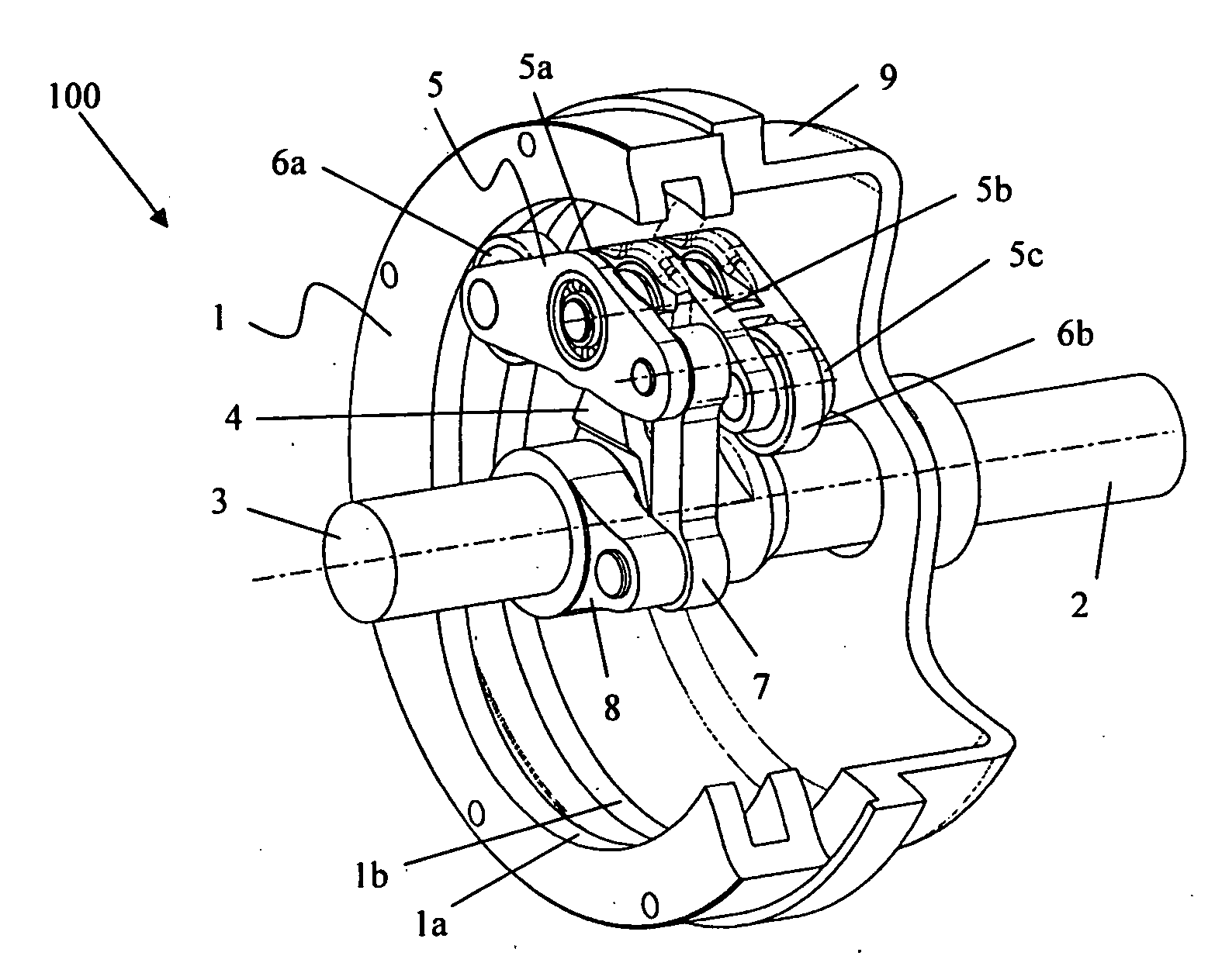
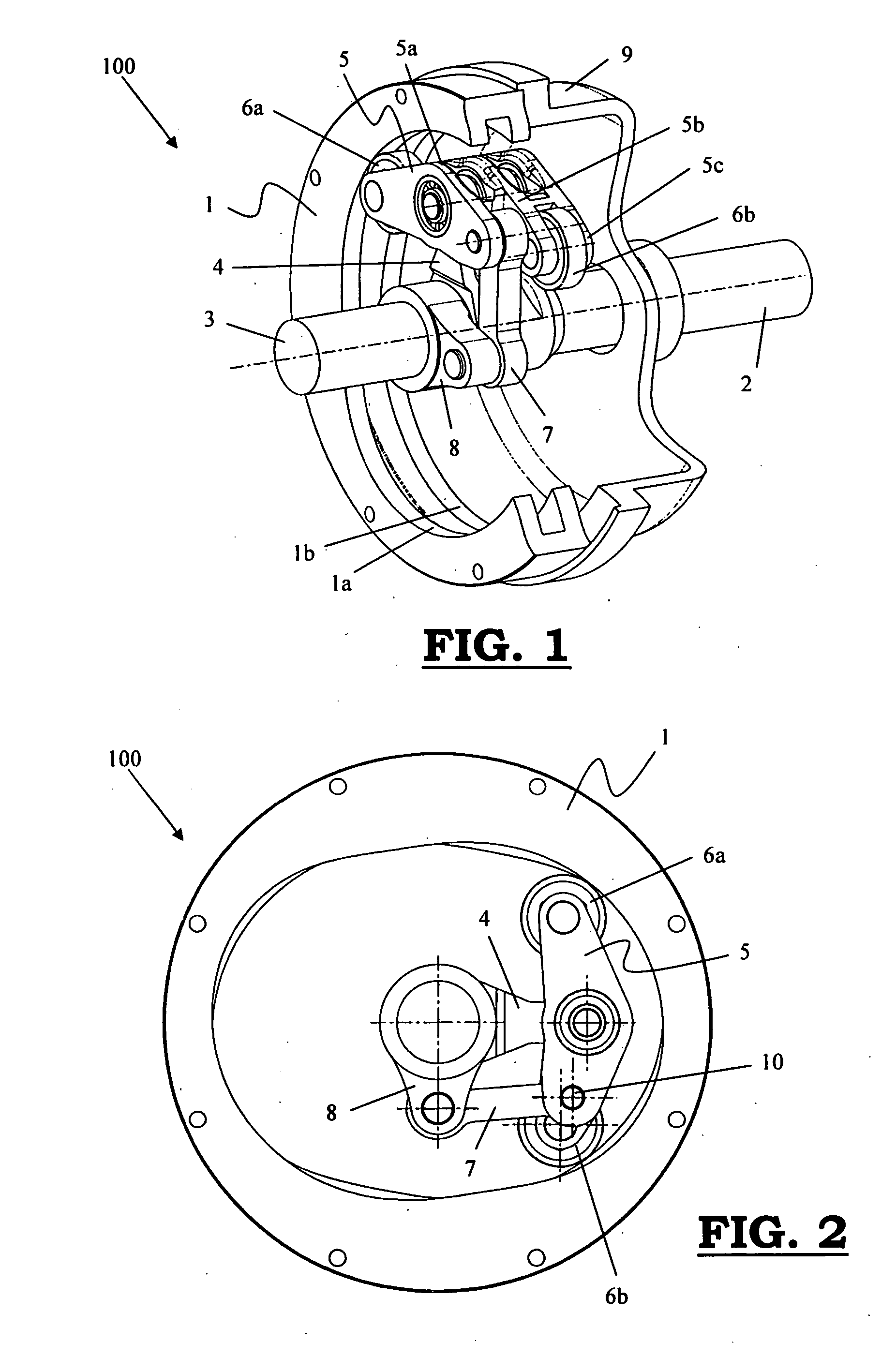
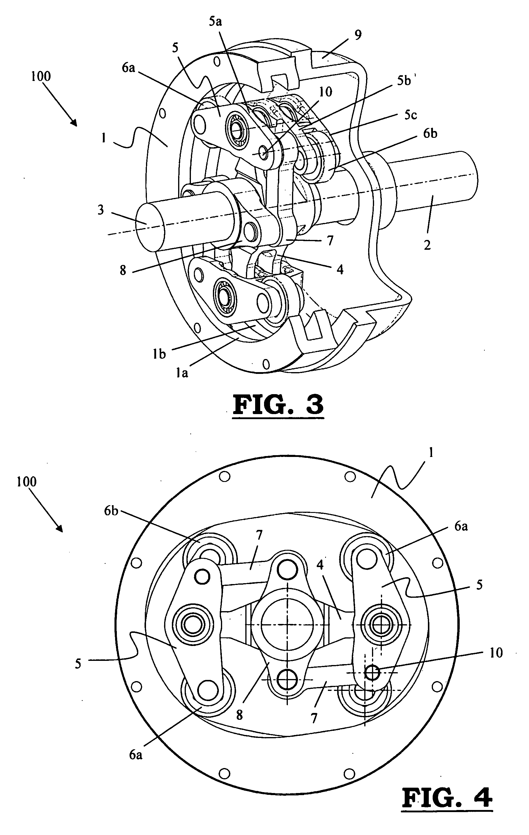
[0068] As represented in the FIGS. 1 up to and including 9, a device (100) according to the invention for modulating a first rotational motion of an input shaft (2) to a second rotational motion, different from the first, of an output shaft (3) in textile machines, is comprising, on the one hand, a fixed complementary cam (1) provided with at least two cam profiles (1a, 1b) and at least one cam follower (5) which is linked to the input shaft and the output shaft (2, 3) and which is provided with at least two contact rollers (6a, 6b), each following a different cam profile (1a, 1b) because of which the said cam followers (5) are performing a rocking motion, on the other hand. The said cam profiles (1a, 1b) are internal cam profiles. The said cam followers (5) are linked to the input shaft (2), preferably in a hinged manner, by means of a support (4). The said cam followers (5) are further driving a link (7, 7a, 7b) which is linked to a support (8) on the output shaft (3) and are impo...


PUM


Abstract

The invention relates to a device for modulating a first rotational motion of an input shaft (2) to a second, different from the first, rotational motion of an output shaft (3) in textile machines, comprising:
    • a fixed complementary cam (1) provided with at least two cam profiles (1a, 1b);
    • at least one cam follower (5), which is linked to the input and the output shafts (2, 3) and which is provided with at least two contact rollers (6a, 6b), each following a different cam profile (1a, 1b), because of which the said cam followers (5) are performing a rocking motion,
wherein the said cam profiles (1a, 1b) are internal cam profiles.

Description

[0001] This application claims the benefit of Belgian Application No. 2005 / 0196 filed Apr. 13, 2005, which is hereby incorporated by reference in its entirety. BACKGROUND OF THE INVENTION [0002] The invention relates to a device for modulating a first rotational motion of an input shaft to a second, different from the first, rotational motion of an output shaft in textile machines, comprising [0003] a fixed complementary cam provided with at least two cam profiles; [0004] at least one cam follower, which is linked to the input and the output shafts and which is provided with at least two contact rollers, each following a different cam profile, because of which the said cam followers are performing a rocking motion. [0005] In textile machines, i.e. weaving machines, Jacquard machines, knitting machines, etc. quite a number of elements are moving in accordance with an oscillating, reciprocating or an irregular rotational motion in connection with a rotating, most of the time continuou...

Claims


Application Information

Patent Timeline
IPC IPC(8): A01B35/00
CPCD03C1/00D03C1/16D03C3/36D03C5/02F16H53/06D03D49/30D03D49/60F16H25/04F16H35/02D03D47/262
Inventor VANDERJEUGT, BRAMTHEOBALD, MATTHEWGRAHAM, JAMES ANTHONY
Owner N V MICHEL VAN DE WIELE
Why Eureka
Try Eureka