High speed airship

a high-speed airship and airframe technology, applied in the field of high-speed airships, can solve the problems of poor performance, poor performance or even disaster, cost and weight of rigid frames, etc., and achieve the effects of reducing aerodynamic drag, precise control of balance and buoyancy, and eliminating the use of ballast weigh

Inactive Publication Date: 2006-10-19
NAGY IMRE
View PDF10 Cites 13 Cited by
  • Summary
  • Abstract
  • Description
  • Claims
  • Application Information

AI Technical Summary

Benefits of technology

[0010] Multiple inflatable chambers are arranged in a multiple tubular cluster to structurally support each other, and to create a centrally located protected tunnel in the center of the airship, where passengers or cargo can be placed. A highly aerodynamic conical shaped rigid frame cabin which incorporates the cockpit and passenger lift is attached to the front end of the airship, and a rigid frame aft cabin incorporate the cargo lift is attached to the aft end of the airship. This design reduces aerodynamic drag, vastly increases passenger safety and makes it possible to land on water, solving the #3 cause of airship disaster.
[0011] The multiple inflatable chambers divided into a multiple inflatable sections, wherein each section has a multiple inner tube. One inner tube is reserved to cont

Problems solved by technology

The drawback of the rigid frame is that it can be damaged easily, especially during hard landing, not to mention the costs and weight of the rigid frame.
Each of these designs can lead to poor performance or even disasters.
#1 cause: Lack of rapid buoyancy control.—The primary buoyancy of the airship is controlled by the volume of the helium, that is too slow to enable significant changes in an emergency, such as those caused by interception with violent storm or turbulent air.—The secondary buoyancy control is by using ballast

Method used


Image

  • High speed airship
  • High speed airship

Examples


Embodiment Construction

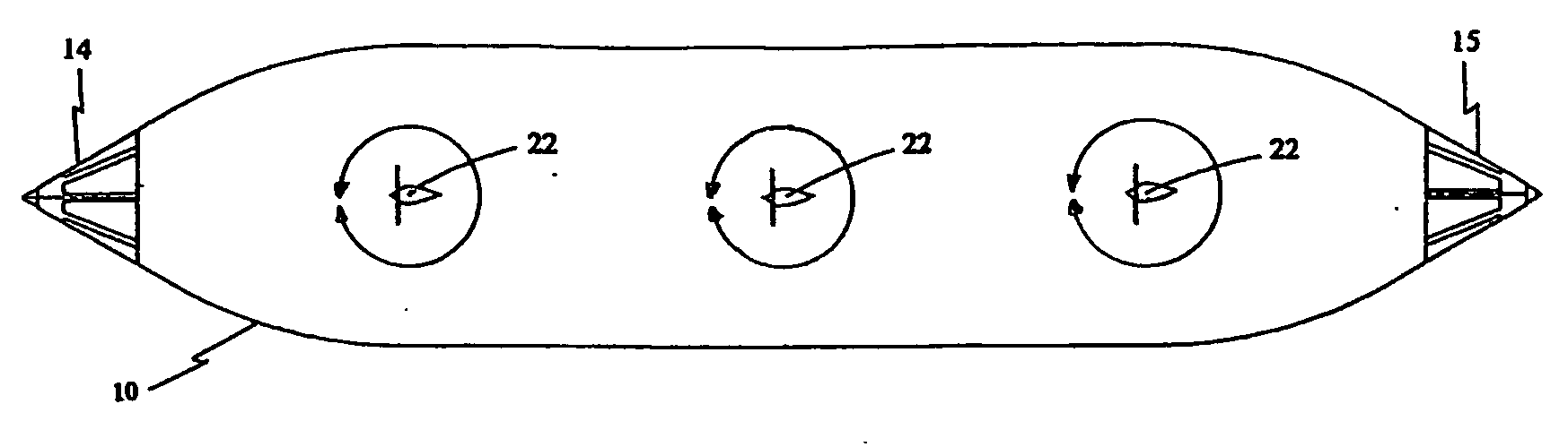
[0016] Referring to FIG. 1, the airship according to the invention comprises:

[0017] Envelope 10, adapted to contain helium or air.

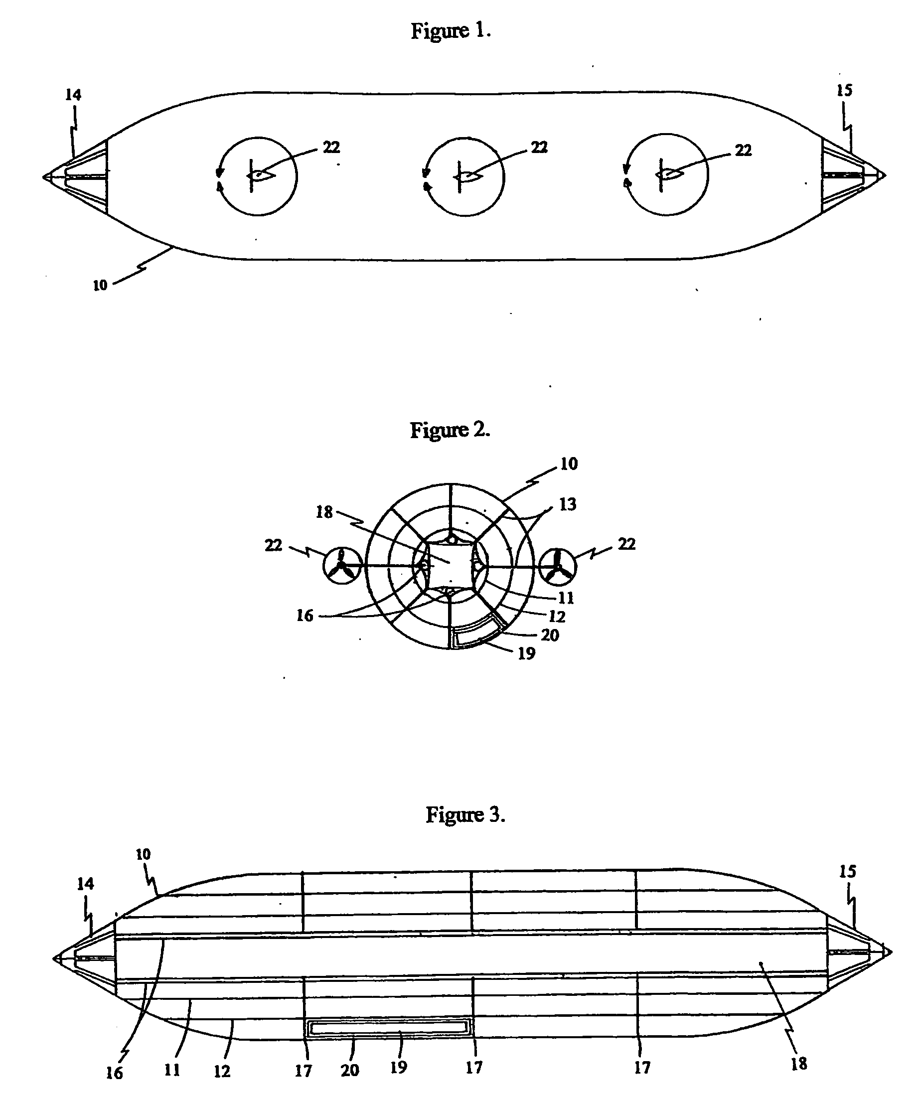
[0018] Passenger or cargo tunnel 18, in the longitudinal center of the envelop 10.

[0019] Rigid frame cabin 14, attached to the front end of the envelop 10.

[0020] Rigid frame aft cabin 15, attached to the aft end of the envelop 10.

[0021] In the preferred embodiment, the airship has six propulsion units 22, three propulsion unit on each side of the envelop 10, each propulsion unit contains engine, propeller and is attached to the envelop with a pivoting shaft so each of the propellers plane of rotation can be independently rotated into any direction of the 360 degree circle.

[0022] Referring to FIG. 2, and FIG. 3, envelop 10, all-fabric structure has:

[0023] Multiple longitudinal dividers 13, are perpendicular to the longitudinal center line of the airship.

[0024] Multiple tubular dividers 11, and 12, which center line same as the airship longitudinal ...


PUM


Abstract

A high speed airship (10) with multiple inflatable chambers (11) arranged in a multiplicity of tubular clusters to enhance structural strength and to create a centrally located passenger or cargo tunnel (18) to increase passenger safety. A conical shaped rigid frame front cabin (14) attached to the front end of the airship, and a conical shape rigid frame aft cabin (15) attached to the aft end of the airship, designed to reduce aerodynamic drag, to achieve high speed, and to be able to land on water. Specially designed multiple sections with multiple inner tubes to increase safety. Helium recovery system to control balance and buoyancy without the loss of helium and to eliminate the use of ballast, which otherwise would reduce lifting capacity. Independently rotateable propulsion units (22) for rapid balance and buoyancy control in emergency and to provide high maneuverability to eliminate the need of ground crew.

Description

BACKGROUND OF THE INVENTION [0001] Most of airships are designed with a rigid frame structure that carries all the load. The drawback of the rigid frame is that it can be damaged easily, especially during hard landing, not to mention the costs and weight of the rigid frame. The passenger cabin is attached under the belly of the airship. [0002] The blimp on the other hand has no rigid frame, the inflated envelop cares all the load. The passenger cabin is attached under the belly of the blimp. [0003] Each of these designs can lead to poor performance or even disasters. [0004] By analyzing airship disasters it becomes clear that: [0005] #1 cause: Lack of rapid buoyancy control.—The primary buoyancy of the airship is controlled by the volume of the helium, that is too slow to enable significant changes in an emergency, such as those caused by interception with violent storm or turbulent air.—The secondary buoyancy control is by using ballast, the most common ballast used is water, but i...

Claims


Application Information

Patent Timeline
IPC IPC(8): B64B1/02B64B1/06B64B1/08B64B1/22B64B1/32B64B1/60
CPCB64B1/06B64B1/08B64B1/60B64B1/32B64B1/22
Inventor NAGY, IMRE
Owner NAGY IMRE
Why Eureka
Try Eureka