Illumination assembly

a technology of assembly and light, applied in the direction of display means, instruments, spectral modifiers, etc., can solve the problems of reducing the purity of white light, raising costs, and other non-white colors may become visible, and achieve the effect of minimal color combination distance and high purity for white ligh

Active Publication Date: 2006-10-19
TCL CHINA STAR OPTOELECTRONICS TECH CO LTD
View PDF4 Cites 24 Cited by
  • Summary
  • Abstract
  • Description
  • Claims
  • Application Information

AI Technical Summary

Benefits of technology

[0008] Therefore, the object of this invention is to provide an illumination assembly having a multi-chip light emitting diode (LED) array in which light emitted from LEDs in the array are effectively combined, thereby obtaining a high degree of purity for white light generated by the array while achieving a minimal color combination distance.

Problems solved by technology

In this configuration, if it is desired to obtain a brightness roughly equal to that obtained using, for example, a cold cathode fluorescent lamp, a large number of the LEDs need to be used, thus raising costs.
Further, if a small number of the LEDs in the cluster arrangement malfunction, the purity of the white light is reduced, and other non-white colors may become visible.
In addition, with this configuration, a color combination distance (i.e., a minimum distance from the LEDs at which the additive color phenomenon takes effect) is approximately 30 mm, which may be considered excessive for some applications.
However, since it is not possible for all three of the LEDs 11 to be positioned on a center axis of the transparent lens, the light emitted from each of the LEDs 11 is skewed in three different directions and is not projected vertically.

Method used


Image

  • Illumination assembly
  • Illumination assembly
  • Illumination assembly

Examples


Embodiment Construction

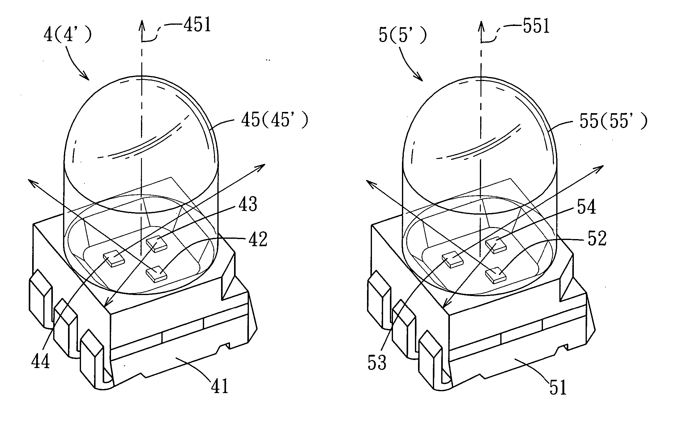
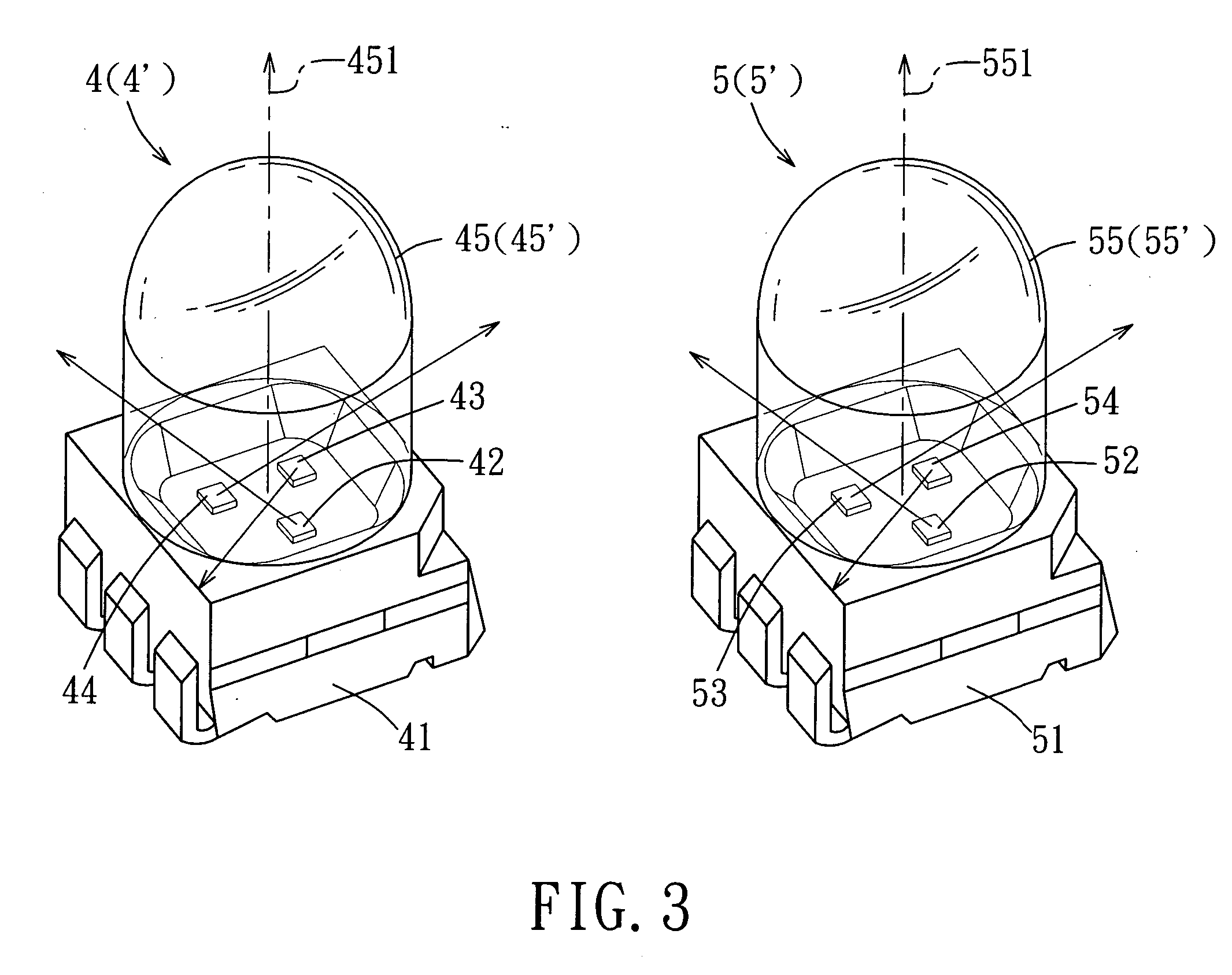
[0021] Referring to FIGS. 3, 4, and 5, an illumination assembly according to a preferred embodiment of the present invention includes a base plate 2, a housing 3, multi-chip light emitting diode (LED) array, and a diffusion sheet 6.

[0022] The multi-chip LED array includes first through fourth multi-chip LED units 4, 4′, 5, 5′ and includes a first diode row. The first diode row are composed by the first multi-chip LED unit 4 and the second multi-chip LED unit 5, which are mounted on the base plate 2. The first multi-chip LED unit 4 includes a red LED 42, a green LED 43, and a blue LED 44, as well as a first transparent lens 45. The second multi-chip LED unit 5 includes a red LED 52, a green LED 53, and a blue LED 54, as well as a second transparent lens 55. Emitted light of each of the red, green, and blue LEDs 42-44 and 52-54 of the first and second multi-chip LED units 4, 5 have a respective primary emission direction along which a majority of the emitted light is projected throug...


PUM


Abstract

An illumination assembly includes a first diode row having first and second multi-chip LED units, and a second diode row having third and fourth multi-chip LED units. The first through fourth multi-chip LED units each includes red, green, and blue LEDs. Light of the red, green, and blue LEDs of the first through fourth multi-chip LED units has a respective primary emission direction (PED). The PEDs of same colored ones of the LEDs of the first and second multi-chip LED units are oriented along one direction. The PEDs of the remaining two LEDs of the first and second multi-chip LED units are oriented in opposite directions from each other. The PEDs of the LEDs of the third and fourth multi-chip LED units are oriented in opposite directions as compared to those of the LEDs of the first and second multi-chip LED units, respectively.

Description

CROSS-REFERENCE TO RELATED APPLICATION [0001] This application claims priority of Taiwanese Application No. 094112379, filed on Apr. 19, 2005. BACKGROUND OF THE INVENTION [0002] 1. Field of the Invention [0003] The present invention relates to an illumination assembly, more particularly to an illumination assembly having a multi-chip light emitting diode (LED) array. [0004] 2. Description of the Related Art [0005] White light may be obtained using LEDs by combining a LED with other materials, or by combining a plurality of differently colored LEDs. As an example of the former method, a blue LED is used in conjunction with a phosphor powder that emits a yellow light when excited. The yellow light emitted by the phosphor powder mixes with the blue light of the LED that has not been absorbed by the phosphor powder to generate white light. In the latter method, an additive color technique is employed by using differently colored LEDs in combination, thus obtaining white light. That is, ...

Claims


Application Information

Patent Timeline
Patent Type & Authority Applications(United States)
IPC IPC(8): G09G3/32
CPCG09G3/32Y10S362/80F21Y2105/003G09G2300/0452F21Y2105/12F21Y2105/10
Inventor CHOU, WEI-JEN
Owner TCL CHINA STAR OPTOELECTRONICS TECH CO LTD
Why Eureka
Try Eureka