Image forming apparatus and its control method, and computer program and computer readable storage medium

a technology of image forming apparatus and control method, which is applied in the direction of recording apparatus, digitally marking record carriers, instruments, etc., can solve the problems of difficult to obtain a high-quality full-color image, high cost, and inability to perform compensation frequently, so as to achieve less deterioration of image quality

Active Publication Date: 2006-10-19
CANON KK
View PDF3 Cites 30 Cited by
  • Summary
  • Abstract
  • Description
  • Claims
  • Application Information

AI Technical Summary

Benefits of technology

[0011] The present invention can provide an image which is free from any moire that may be caus

Problems solved by technology

On the other hand, a shifting amount of color problem occurs due to shifting amounts of color of respective colors on a transfer sheet resulting from errors of the accuracy of position and diameters of photosensitive bodies, and errors of accuracy of position of optical systems, and it is difficult to obtain a high-quality full-color image.
However, this method poses the following problems.
For this purpose, high-precision movable members are required, resulting in high cost.
Furthermore, since it takes much time until compensation is completed, it is impossible to frequently perform compensation.
However, an optical path length difference may change along with an elapse of time due to temperature rise of mechanical components.
In such case, it becomes difficult to prevent shifting amount of color by compensating the optical path of the optical system.
Second, in order to compensate the image write start position, it is possible to conduct shifting amount of color compensation of t

Method used


Image

  • Image forming apparatus and its control method, and computer program and computer readable storage medium
  • Image forming apparatus and its control method, and computer program and computer readable storage medium
  • Image forming apparatus and its control method, and computer program and computer readable storage medium

Examples


first embodiment

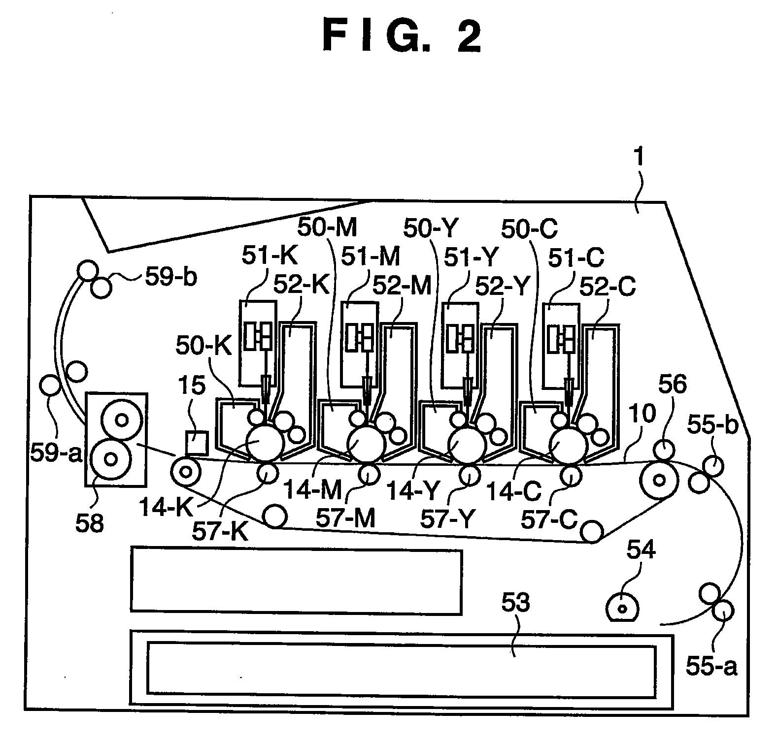
[0045]FIG. 2 is a schematic sectional view for explaining the arrangement of an image forming apparatus according to a preferred embodiment of the present invention. As shown in FIG. 2, the image forming apparatus according to this embodiment has a structure of a four-drum type color laser beam printer.

[0046] This image forming apparatus mounts a transfer medium cassette 53 in a lower portion of the right side surface of the main body. Printing media, printing paper sheets, transmitting sheets, or the like set in the transfer medium cassette 53 are picked up one by one by a feeding roller 54, and the picked-up medium is fed to image forming units by guide roller pairs 55-a and 55-b. In the image forming units, a transfer feeding belt 10 that feeds the transfer medium is stretched flat via a plurality of rotary rollers in the transfer medium feeding direction (from the right to the left in FIG. 2). The transfer medium is electrostatically attracted on the most upstream portion of th...

second embodiment

[0141] The second embodiment will be described below. In the first embodiment, the processing in the color density converter 807 has been described with reference to FIGS. 7A to 7F, FIGS. 18A to 18F, and FIGS. 19A to 19F. In the above description, there are three different compensation amount tables (704, 1804, and 1904). The compensation amount table to be used in the color density conversion processing can be determined based on a feature of image information extracted by the smoothing determination unit 806. The processing in the smoothing determination unit 806 will be described below with reference to FIG. 25.

[0142]FIG. 25 is a block diagram showing an example of the detailed arrangement of the smoothing determination unit 806 according to this embodiment. Referring to FIG. 25, reference numerals 2501a to 2501c denote comparators, which compare predetermined smoothing patterns 2505a to 2505c stored in the smoothing determination pattern memory 805 with image data output from t...

third embodiment

[0156] In the first and second embodiments, after color conversion by the color conversion unit 405, image data is temporarily stored in the bitmap memory 406, and then undergoes address conversion in the shifting amount of color compensation unit 408. By contrast, this embodiment will explain a case wherein the address conversion is made when image data is mapped on the bitmap memory.

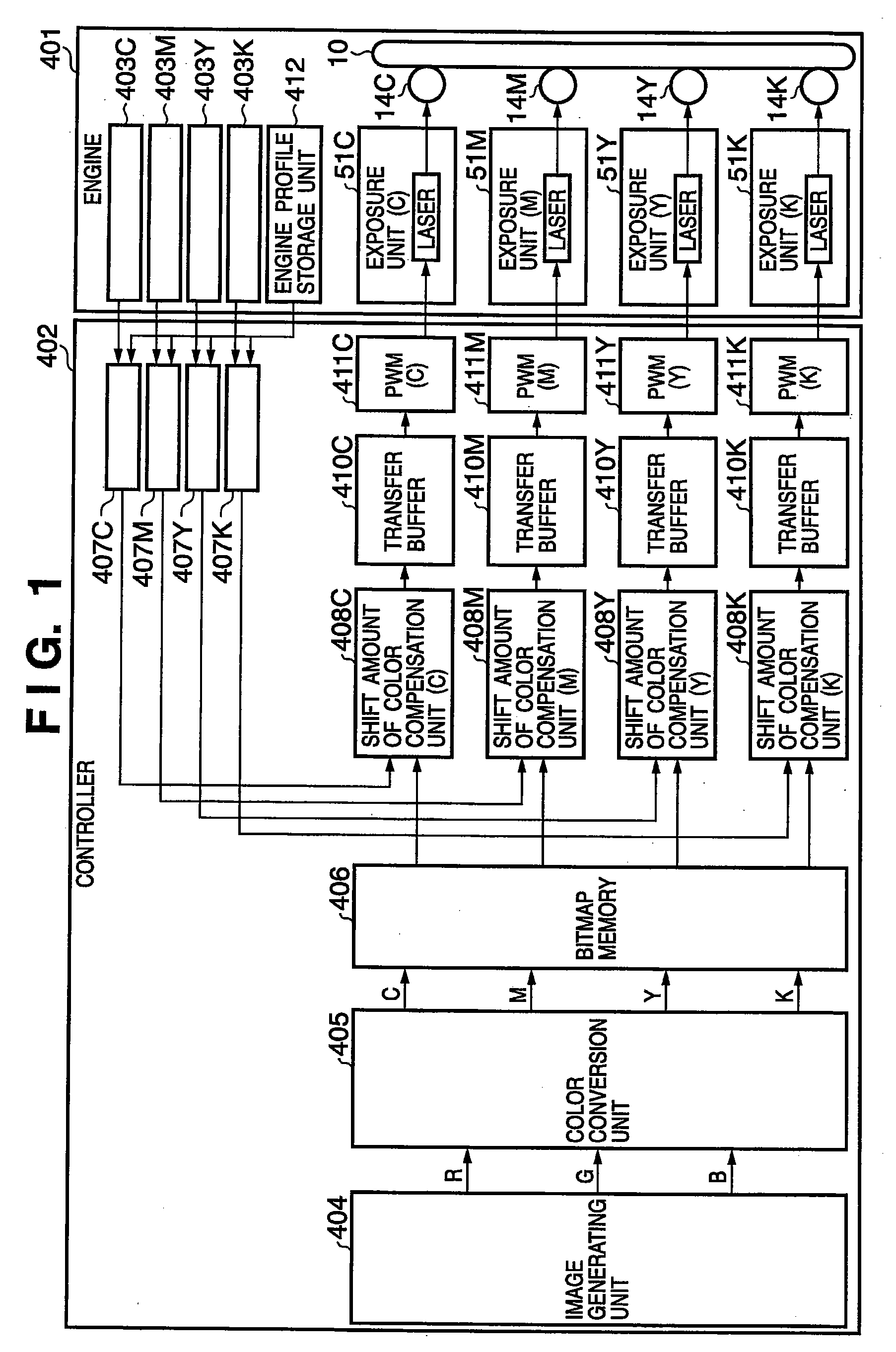
[0157]FIG. 21 is a block diagram showing an example of the arrangement of a printer engine and controller of an image forming apparatus according to this embodiment. The arrangement shown in FIG. 21 is substantially the same as that in FIG. 1, except that address converters 2109 are arranged before a bitmap memory 2106.

[0158] Each address converter 2109 executes compensation processing of the integer part of the compensation amount Δy, i.e., reconstruction processing in the pixel unit in the sub-scan direction, based on the table data 1609 (corresponding to the compensation amount Δy) obtained from t...


PUM


Abstract

A shifting amount of color compensation amount is calculated based on a shifting amount of color obtained from a shifting amount of color storage unit for each image forming unit, and shifting amount of color compensation in the pixel unit is performed by executing address conversion using the calculation result. A feature of an image to be processed is detected, and color density conversion compensation for performing shifting amount of color compensation in less than the pixel unit is performed according to the detected feature. Furthermore, half-tone processing or exceptional processing is selectively executed according to the detected feature.

Description

FIELD OF THE INVENTION [0001] The present invention relates to an image forming apparatus and its control method, and a computer program and computer-readable storage medium. BACKGROUND OF THE INVENTION [0002] A conventional color image forming apparatus using an electrophotography method normally adopts the following system. That is, a single photosensitive body undergoes development of colors using a plurality of developing units, and an exposure-development-transfer process is repeated a plurality of times, thus overlaying and forming color images on a single transfer sheet. The color images are fixed to obtain a full-color image. [0003] According to this system, an image forming process must be repeated three or four times (if black is used), and it takes much time. As a method of removing such shortcomings, the following method is known. That is, a plurality of photosensitive bodies are used, and toner images obtained for respective colors are overlaid in turn on a transfer she...

Claims


Application Information

Patent Timeline
IPC IPC(8): B41J2/205
CPCH04N1/40062H04N1/506H04N1/4056
Inventor KITAMURA, HIROKIAKIBA, YOSHIYUKITAKADA, TSUTOMUNAKAMURA, SHUICHIYAMAMOTO, YUSUKEMOTOYAMA, MASANAOAKIYAMA, TAKESHITOJIMA, KENZONAGAOKA, TAKAAKI
Owner CANON KK
Why Eureka
Try Eureka