Image processing apparatus, image processing method, and program
a technology of image processing and image processing, applied in the field of image scanning apparatuses, image scanning methods, computer programs, can solve the problems of decrease in compression ratio in information compression, and inability to yield fine images, etc., to ensure the reliability of documents and suppress the effect of increasing size and cos
- Summary
- Abstract
- Description
- Claims
- Application Information
AI Technical Summary
Benefits of technology
Problems solved by technology
Method used
Image

Examples
first exemplary embodiment
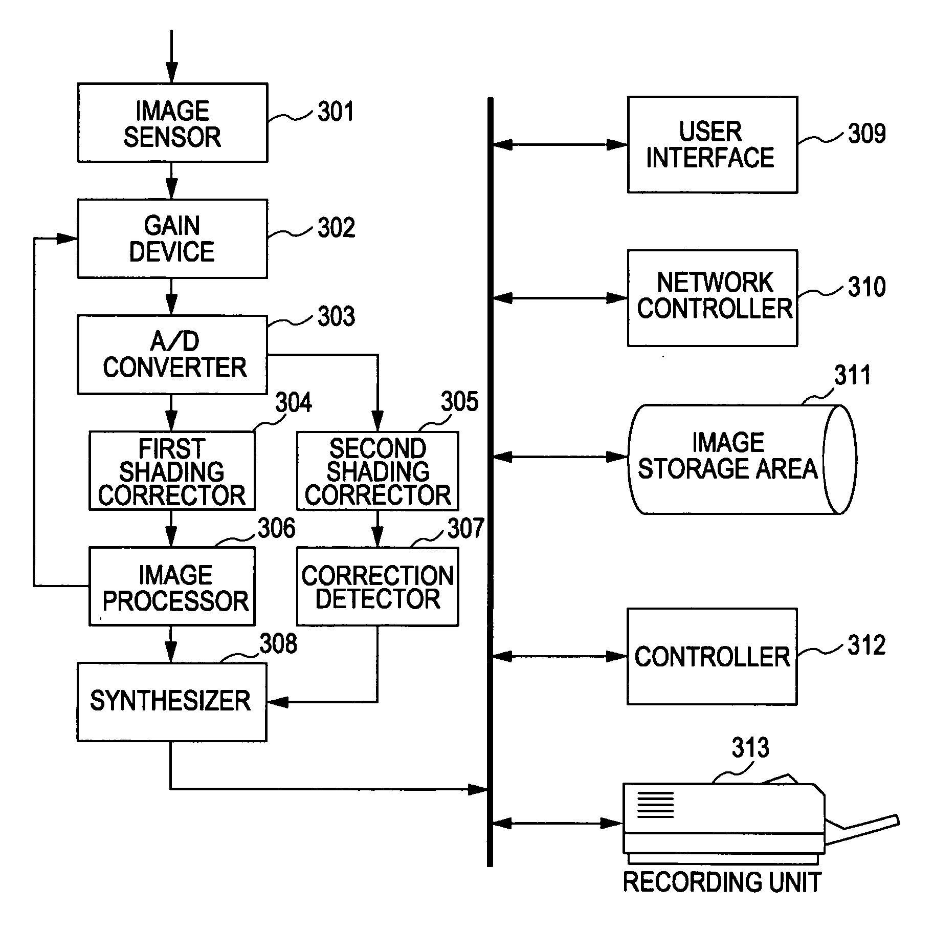
[0066]FIG. 3 is a block diagram showing an example of the configuration of an image forming apparatus according to a first exemplary embodiment of the present invention. An image sensor 301 converts an image of a document into a voltage. A gain device 302 applies a gain to the voltage of the image sensor 301, which voltage is increased to a desired voltage. An A / D converter 303 converts the voltage into digital information. A first shading corrector 304 is used for yielding a correct image luminance by a common method. A second shading corrector 305 performs the shading correction in consideration of the luminance of correction fluid.
[0067] An image processor 306 performs image processing for the information supplied from the first shading corrector 304 by a common method to yield a fine image. The image processor 306 performs, for example, edge enhancement and unsharp mask for finely displaying characters, Moire correction for reducing Moire patterns, and / or change of resolution a...
second exemplary embodiment
[0110] According to the first exemplary embodiment, the correction detector 307 uses the output from the second shading corrector 305 to detect any correction fluid trace and outputs positional information of the corrected portion or the corrected image.
[0111] In contrast, according to a second exemplary embodiment, a correction detector uses the outputs from a first shading corrector and a second shading corrector to detect any correction fluid trace and outputs positional information of the corrected portion or the corrected image.
[Exemplary Configuration]
[0112]FIG. 12 is a block diagram showing an example of the configuration of an image forming apparatus according to the second exemplary embodiment of the present invention. An image sensor 1201 converts an image of a document into a voltage. A gain device 1202 applies a gain to the voltage of the image sensor 1201, which voltage is increased to a desired voltage. An A / D converter 1203 converts the voltage into digital informa...
third exemplary embodiment
[0161] According to the first exemplary embodiment, the correction detector 307 uses the output from the second shading corrector 305 to detect any correction fluid trace and outputs positional information of the corrected portion or the corrected image.
[0162] In contrast, according to a third exemplary embodiment, the second scan output from one shading corrector is used to detect any correction fluid trace and outputs positional information of the corrected portion or the corrected image.
[Exemplary Configuration]
[0163]FIG. 16 is a block diagram showing an example of the configuration of an image forming apparatus according to the third exemplary embodiment of the present invention. Referring to FIG. 16, an image sensor 1601 converts an image of a document into a voltage. A gain device 1602 applies a gain to the voltage of the image sensor 1601, which voltage is increased to a desired voltage. An A / D converter 1603 converts the voltage into digital information. A shading correct...
PUM
 Abstract
Description
Claims
Application Information
 - R&D
- Intellectual Property
- Life Sciences
- Materials
- Tech Scout
- Unparalleled Data Quality
- Higher Quality Content
- 60% Fewer Hallucinations
Browse by: Latest US Patents, China's latest patents, Technical Efficacy Thesaurus, Application Domain, Technology Topic, Popular Technical Reports.
© 2025 PatSnap. All rights reserved.Legal|Privacy policy|Modern Slavery Act Transparency Statement|Sitemap|About US| Contact US: help@patsnap.com