Method at a radiation therapy system

a radiation therapy system and positioning system technology, applied in the field of radiation therapy, can solve the problems of increasing production costs, affecting the quality of products, and affecting the patient's comfort, so as to reduce the amount of work and the space needed, and ensure the accuracy of the calibrated system. , the effect of high accuracy

Active Publication Date: 2006-10-19
ELEKTA AB
View PDF5 Cites 13 Cited by
  • Summary
  • Abstract
  • Description
  • Claims
  • Application Information

AI Technical Summary

Benefits of technology

[0010] Thus, embodiments of the present invention are based on the insight of determining the angular and linear offset between the motional axes of a patient positioning system and a coordinate system defining a treatment volume, and furthermore determining the radiation focus point in relation to the patient positioning system. Accordingly, the position of the focus point in relation to the coordinate system defining the treatment volume is provided via the patient positioning system. Thereby, a correct and accurate positioning of the treatment volume within a patient vis-à-vis the radiation focus point is enabled by using the acquired offset information for compensating, in the movement or positioning of the motional axes of the positioning system during the radiation treatment, for determined angular and linear offsets of the positioning system.
[0011] One major advantage resulting from embodiments of the present invention is that the calibration of the motional axes of the patient positioning system can suitably be performed when manufacturing the positioning system, i.e. at the manufacturing plant. Upon assembling the radiation therapy system at the medical facility where the radiation therapy is to be administered, generally a hospital, the actual position of the fixed radiation focus point in relation to the fixation unit coordinate system is measured, and the radiation therapy system is ready for use without the need for subsequent calibration of the positioning system. Thus, embodiments of the invention reduces the need for calibration of the positioning system “on site”, which entails several advantages. Since the calibration is made in connection with manufacture of the positioning system, any discrepancies discovered during calibration could easily be attended to without the need for shipping personnel and equipment to a sometimes distant medical facility.
[0012] Furthermore, calibration performed in a manufacturing facility enables the use of advanced and precise calibration and measurement tools, which may be difficult or very expensive to ship and possibly unsuitable or even impossible to use at a hospital. An extensive and highly accurate verification of the precision of the calibrated system is enabled if performed in a manufacturing facility, thus providing a better product. It also reduces the amount of work and the space needed during installation of the system at a hospital. The installation personnel do not need to be experts in the calibration of the positioning system. Instead, the installation personnel can focus on the verification of the entire system, i.e. after having mounted the positioning system to the radiation therapy unit.

Problems solved by technology

However, tissue destruction occurs where the radiation beams from all radiation sources intersect or converge, causing the radiation to reach tissue-destructive levels.
A drawback of the system is that the patient may experience some discomfort when the head is moved while the body is kept still.
Since improved constructional tolerances normally result in increased production costs, especially when producing a system comprising co-operating moving parts, such a positioning system would be very expensive to produce.

Method used


Image

  • Method at a radiation therapy system
  • Method at a radiation therapy system
  • Method at a radiation therapy system

Examples


Embodiment Construction

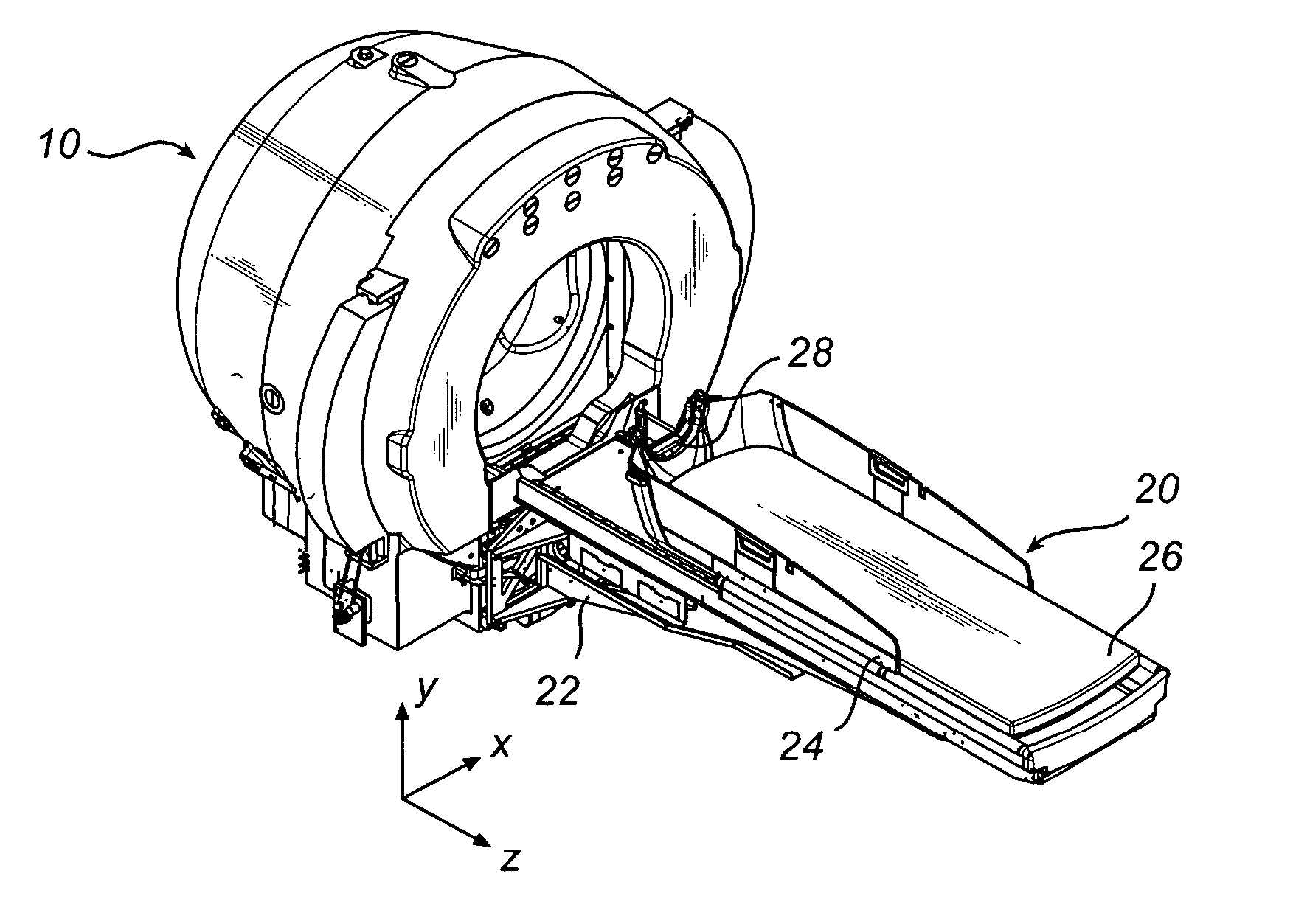
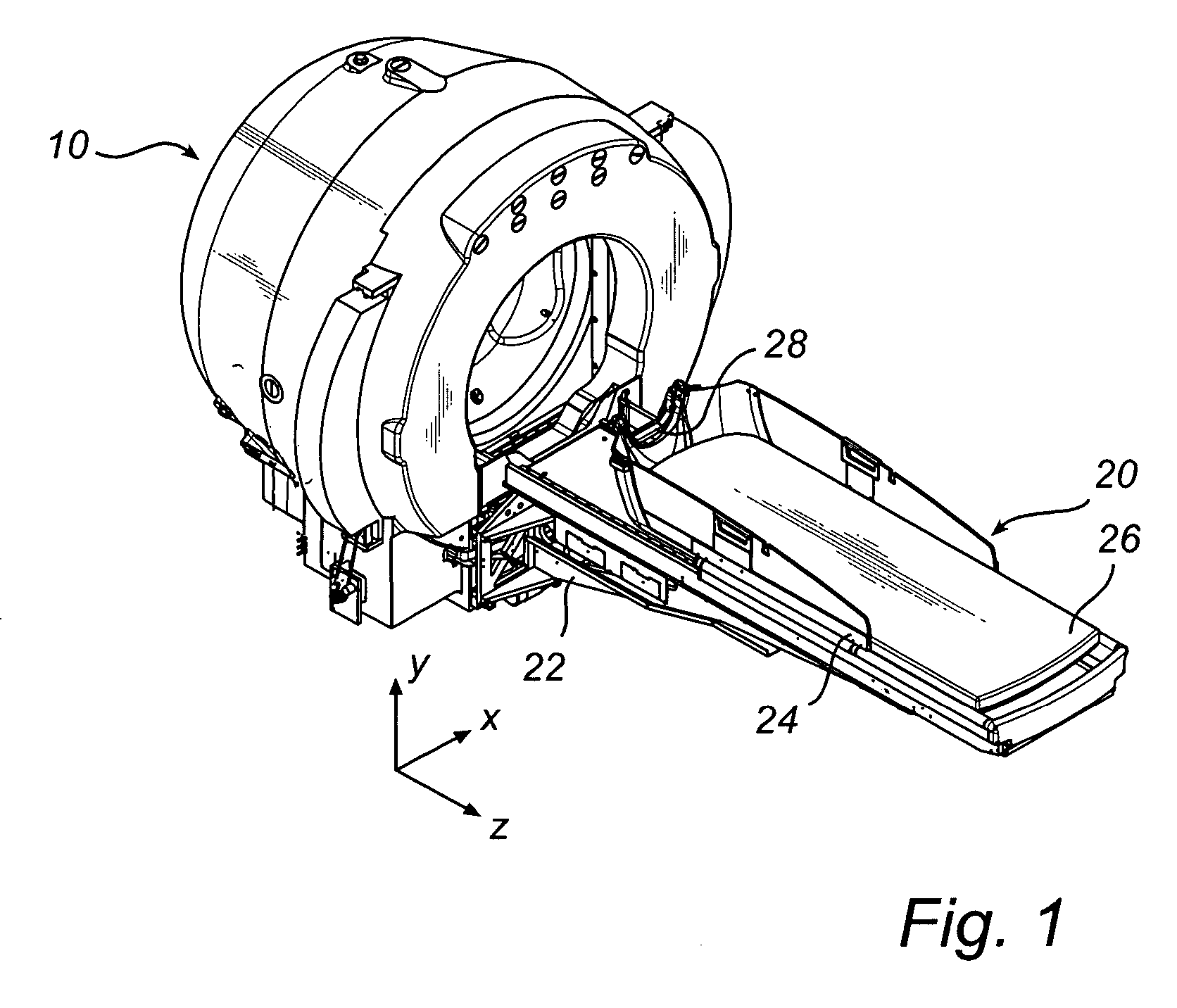
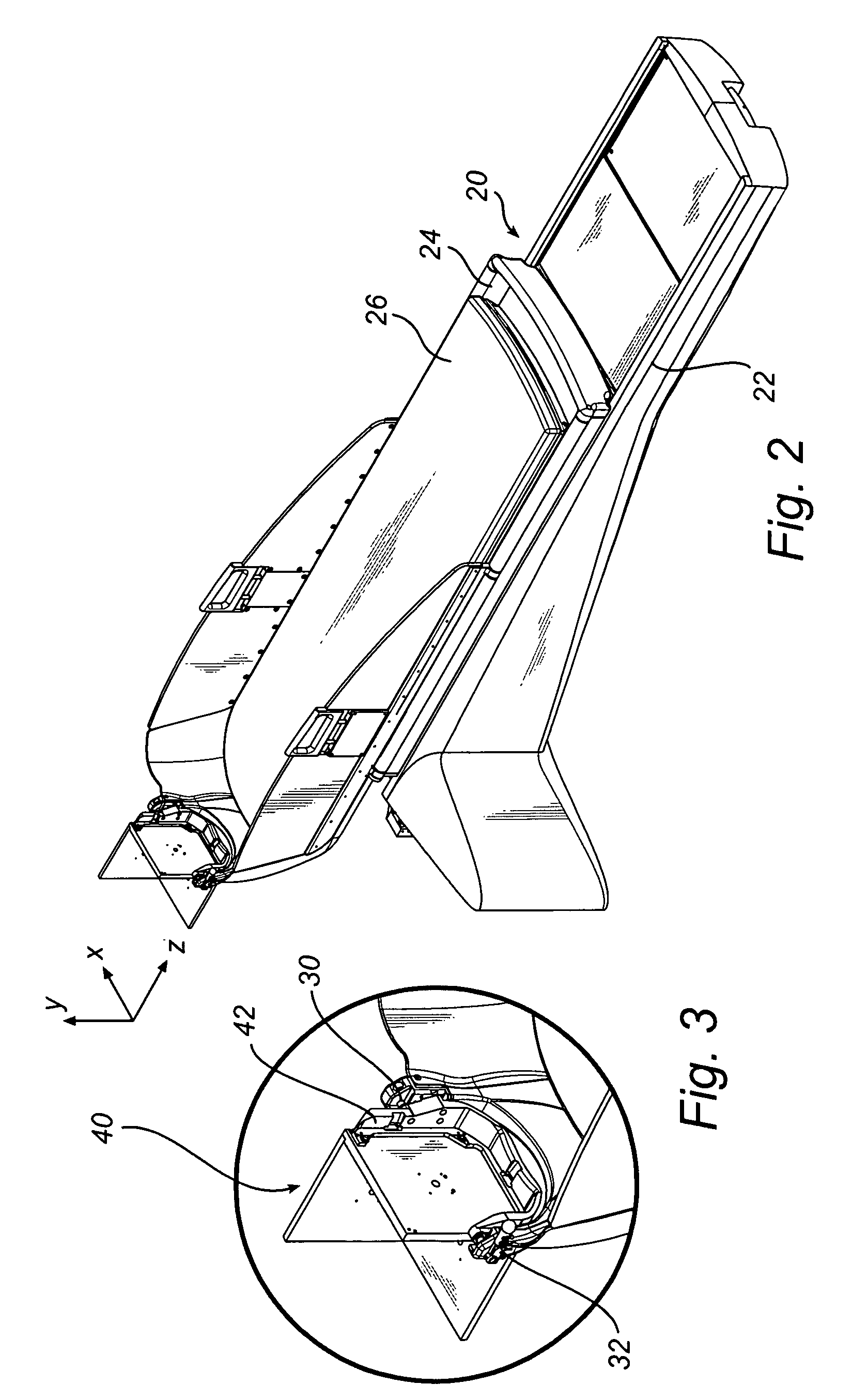
[0041] With reference to FIGS. 1-6, a radiation therapy system for which the present invention is applicable comprises a radiation unit 10 and a patient positioning unit 20. In the radiation unit 10, there are provided radioactive sources, radioactive source holders, a collimator body, and external shielding elements. The collimator body comprises a large number of collimator channels directed towards a common focus point, in a manner as is commonly known in the art.

[0042] The collimator body also acts as a radiation shield preventing radiation from reaching the patient other than through the collimator channels. Examples of collimator arrangements in radiation therapy systems applicable to the present invention can be found in WO 2004 / 06269 A1, which is hereby incorporated by reference. However, the present invention is also applicable to radiation therapy systems using other arrangements for collimating radiation into a fixed focus point, such as is disclosed in U.S. Pat. No. 4,7...


PUM


Abstract

Calibration of a radiation therapy system comprising a radiation unit with a fixed focus point, a fixation unit for fixing a treatment volume in a patient, and a positioning system. The positioning system comprises a fixed framework, a movable carriage for carrying and moving the entire patient, motor(s), a control system for controlling the motor(s), and at least one engagement point for releasably mounting the fixation unit in fixed engagement with the positioning system. A fixation unit coordinate system defined in relation to the fixation unit is provided. Linearity errors for the motional axes of the carriage and the angular offset between the motional axes and the coordinate system is determined, whereby the relationships between the axes of the coordinate system and the motional axes of the positioning system are determined. The positioning system is then mounted in fixed relationship with the radiation therapy unit and the focus point in relation to the positioning system is determined, whereby the relationship between the focus point and the coordinate system is also determined.

Description

CROSS REFERENCE TO RELATED APPLICATIONS [0001] This application claims the benefit of Swedish Patent Application No. 0500834-7, filed on 14 Apr. 2005. FIELD OF THE INVENTION [0002] The present invention relates to the field of radiation therapy. In particular, the invention concerns a method of calibrating a positioning system in a radiation therapy system comprising a radiation therapy unit having a fixed radiation focus point. BACKGROUND OF THE INVENTION [0003] The development of surgical techniques have made great progress over the years. For instance, for patients requiring brain surgery, non-invasive surgery is now available which is afflicted with very little trauma to the patient. [0004] One system for non-invasive surgery is sold under the name of Leksell Gamma Knife®, which provides such surgery by means of gamma radiation. The radiation is emitted from a large number of fixed radioactive sources and are focused by means of collimators, i.e. passages or channels for obtaini...

Claims


Application Information

Patent Timeline
Patent Type & Authority Applications(United States)
IPC IPC(8): G21K5/08
CPCA61N5/1084A61N5/1049
Inventor CARLSSON, PERHEDIN, LARS
Owner ELEKTA AB
Why Eureka
Try Eureka