Compaction monitoring system
a monitoring system and compacting technology, applied in the field of compacting monitoring system, can solve the problems of exacerbated problems, deformation of compactable sediments (or tectonically active areas), and catastrophic loss of producing zones up to and including the loss of a whole well
- Summary
- Abstract
- Description
- Claims
- Application Information
AI Technical Summary
Benefits of technology
Problems solved by technology
Method used
Image
Examples
example 1
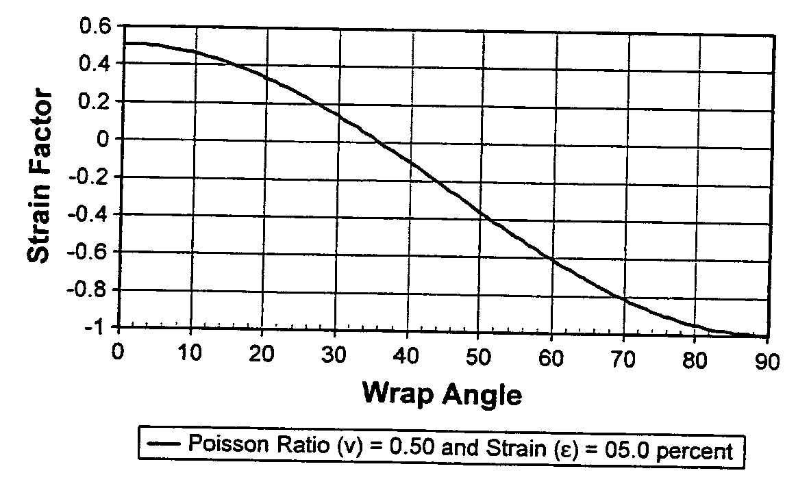
[0097]FIG. 6, illustrates the resulting wavelength response, relative to each numbered transducer, from a cylindrical structure undergoing offset shear in a controlled test. The cylindrical structure is three (3) inches in diameter and twenty-four (24) inches long. Although the transducer spacing along the optical fiber in this test is about 1 centimeter, a spacing of 2 centimeters may be adequate to measure the same shear response in a cylindrical structure with the same diameter. A preferred wrap angle of about 20 degrees was used. The detectable variation in wavelength response, representing lateral offset, was between 0.001 inches up to about 0.600 inches.
[0098] In this example, a 0.001-inch lateral offset translates into a dogleg in the structure of about less than one-half degree for each one hundred-foot section of the structure, which is inconsequential. However, a lateral offset of about 0.1 inch over the same length of structure translates into a dogleg of approximately 4...
example 2
[0103] In this example, accurate measurements of low strain and high sensitivity to bending or buckling induced by axial compaction are important objectives. A thin-walled PVC pipe was tested using the weight of the pipe, horizontally suspended by its ends, as the applied force. A preferred wrap angle of about 20 degrees was used to apply the transducers and optical fiber to a 10-foot long section of the pipe with a 6.5-inch diameter. A 5-centimeter transducer spacing was used to resolve the wavelength response from a buckle or a bend.
[0104] In FIG. 8, the wavelength response resulting from the lateral force applied by the weight of the pipe is illustrated. A maximum lateral offset of about 0.07 inches was detected. The wavelength response in FIG. 8 clearly reveals a bend or a buckle because one period or cycle of the wavelength response corresponds to one wrap of the fiber. A 0.07-inch lateral offset represents less than a 7-degree bend or buckle for each one hundred-foot section ...
example 3
[0105] In this example, the same pipe was tested using a weight hung from the center of the pipe, which was horizontally suspended at each end. The lateral offset due to a bend is about 0.228 inches. As illustrated in FIG. 9, a relatively clean periodic signal is apparent everywhere except at the ends and at the center of the wavelength response where the weight is hanging and distorting the signal. The distorted signals are a special case related to pipe crushing caused by local loading on the pipe.
[0106]FIG. 10 represents a simple illustration of a lateral force on the structure 10 induced by axial compaction. Here the structure 10 is subjected to a lateral force 310 on one side of the structure 10. The wavelength response, representing strain on the structure 10 measured by transducers 20, associated with the lateral force 310 is periodic and approximately sinusoidal as illustrated in FIG. 10A. The period of the wavelength response or signal is equal to about one cycle per wrap ...
PUM
 Abstract
Description
Claims
Application Information
 - R&D
- Intellectual Property
- Life Sciences
- Materials
- Tech Scout
- Unparalleled Data Quality
- Higher Quality Content
- 60% Fewer Hallucinations
Browse by: Latest US Patents, China's latest patents, Technical Efficacy Thesaurus, Application Domain, Technology Topic, Popular Technical Reports.
© 2025 PatSnap. All rights reserved.Legal|Privacy policy|Modern Slavery Act Transparency Statement|Sitemap|About US| Contact US: help@patsnap.com


