Camera system for attaching lens unit to electronics device

a technology for electronics devices and cameras, applied in the field of cameras, can solve the problems of difficulty in handling for beginners and sometimes required technical knowledge, and achieve the effects of improving the usability of the camera system, simplifying the operation of attaching and detaching the lens unit, and similar simplicity

Inactive Publication Date: 2006-10-19
FUJIFILM CORP +1
View PDF3 Cites 88 Cited by
  • Summary
  • Abstract
  • Description
  • Claims
  • Application Information

AI Technical Summary

Benefits of technology

[0014] According to the camera system of the present invention, a shooter can attach the lens unit to a desired position of the electronics device. In virtue of this, for example, when the electronics device is a camera body, it is possible to freely change a grasp area of the camera body. Further, in this case, it is possible to shoot a subject residing in a direction different from a front direction of the camera body. Usability of the camera system is improved.
[0015] When the attachment device comprises the magnet and the magnetic material, it is possible to attach the lens unit only by bringing the lens unit close to the electronics device and it is possible to detach the lens unit only by separating the lens unit from the electronics device. Thus, attaching and detaching operations of the lens unit are very simplified. When the attachment device comprises the spikey-hooks sheet and the fuzzy-loops sheet, the attaching and detaching operations of the lens unit are similarly simplified. When the attachment device is the adhesive member, the attaching and detaching operations of the lens unit are similarly simplified. Incidentally, attaching the sheets and the adhesive member to the lens unit and / or the electronics device are very easy.
[0016] Since the attachment detection device and the controller are provided, the preparative operation for shooting is executed after detecting the attachment of the lens unit so that consumption of the electric power may be reduced.
[0017] When the electric power is transferred from the electronics device to the lens unit in the cableless manner, a power cable for transferring the electric power is unnecessary so that an operation for connecting the power cable is eliminated. In the meantime, when the communication device adopts the radio communication, a communication cable is unnecessary so that an operation for connecting the communication cable is eliminated. When the camera system adopts the cableless manner, usability thereof is further improved.

Problems solved by technology

Thus, technical knowledge is sometimes required and there arises a problem in that handling is difficult for beginners.

Method used


Image

  • Camera system for attaching lens unit to electronics device
  • Camera system for attaching lens unit to electronics device
  • Camera system for attaching lens unit to electronics device

Examples


first embodiment

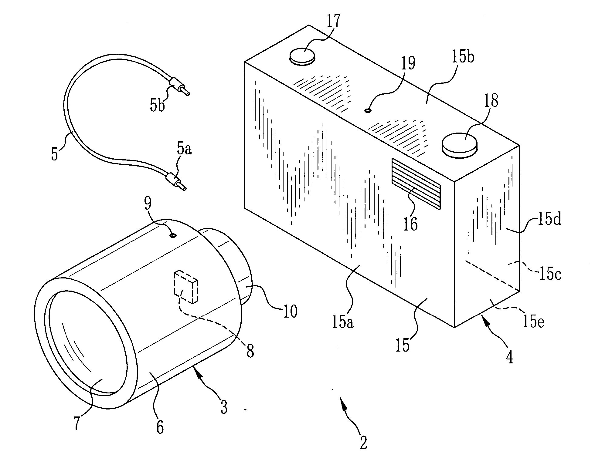
[0033] As shown in FIG. 1, a camera system 2 is composed of a lens unit 3 and a camera body (electronic device) 4 to which the lens unit 3 is attached. The lens unit 3 and the camera body 4 are connected via a cable 5 so that data transmission and power transfer are performed between them.

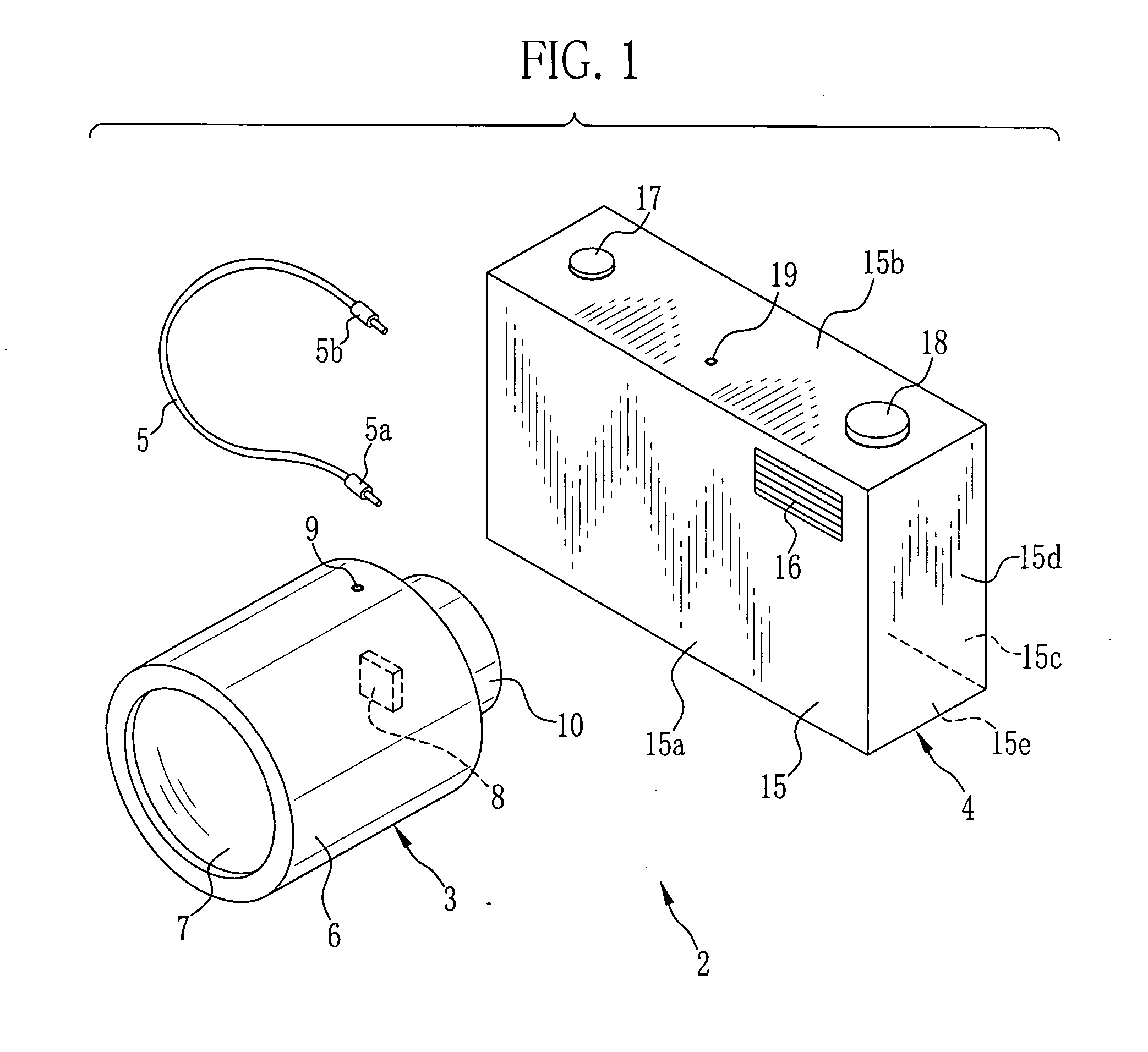
[0034] The lens unit 3 includes a lens barrel 6 containing a taking lens 7 and a CCD 8 for taking a subject image formed by the taking lens 7. An outer surface of the lens barrel 6 is provided with a connecting terminal 9 to which one end 5a of the cable 5 is connected. As shown in FIG. 2, a rear side of the lens barrel 6 is provided with a cylindrical protrusion 10. Magnets 11 are fitted into a rear portion of the protrusion 10. The inside of the lens unit 3 is sealed so that dust or the like is prevented form intruding therein.

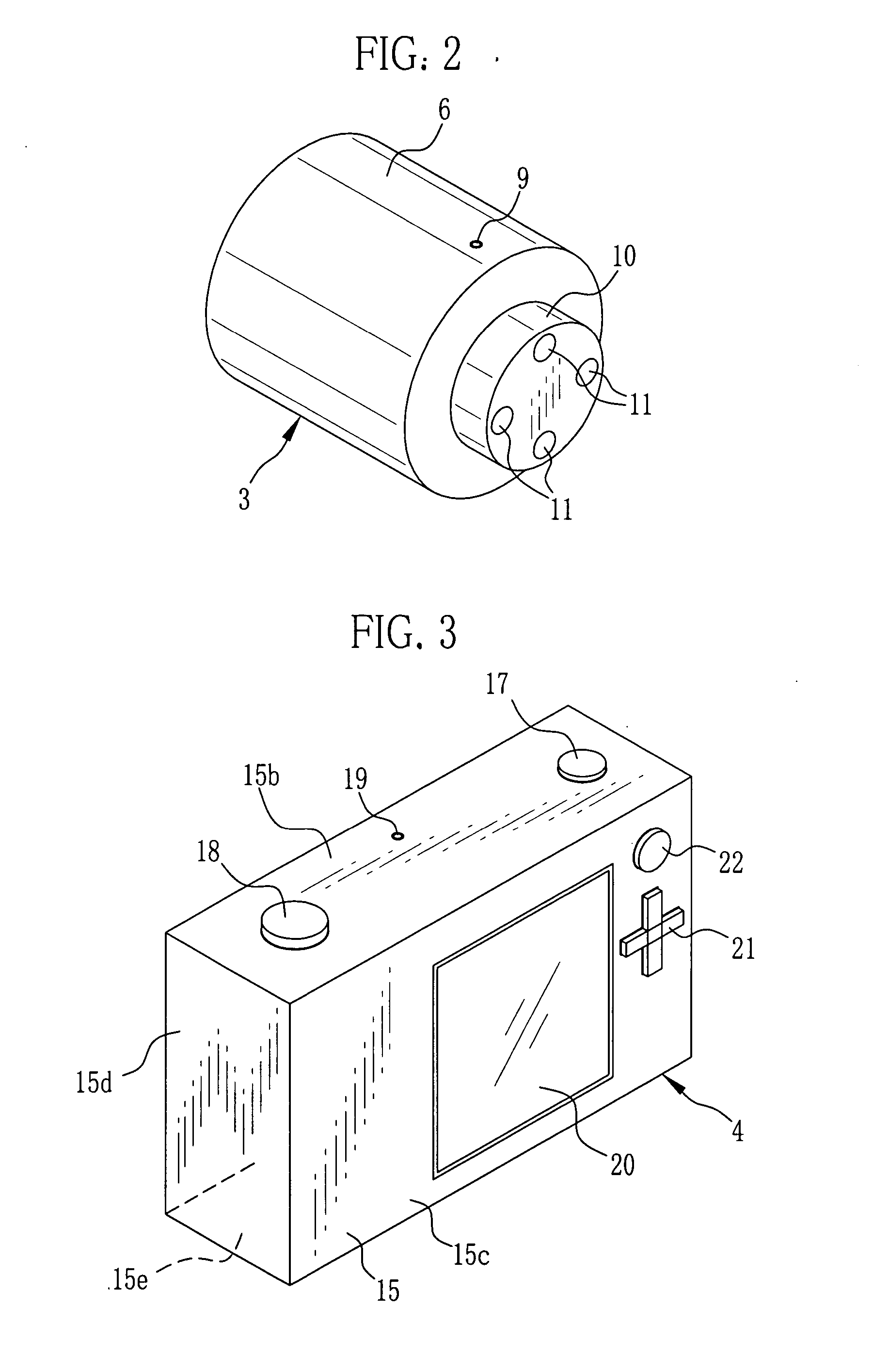
[0035] As shown in FIG. 1, the camera body 4 includes a case 15 having a front wall 15a, an upper wall 15b, a rear wall 15c, a side wall 15d and a bottom wall 15e. The ca...

second embodiment

[0060] This embodiment relates to another camera system having a structure different from the first embodiment. The camera system of the first embodiment uses the magnet and the magnetic material to attach the lens unit. However, the camera system of the second embodiment uses a hook and loop fastener as an attachment member. In the description concerning the second embodiment, a component identical with that of the first embodiment is denoted by the same reference numeral and the description thereof is omitted.

[0061] As shown in FIG. 10, the camera system 100 is composed of the lens unit 3 and the camera body 4. A tape 101 of spikey hooks is attached to the rear surface of the protrusion 10 of the lens unit 3. Moreover, a tape 102 of fuzzy loops is attached to the surface of the front wall 15a of the camera body 4 so as not to overlap with the flash emitting portion 16. To the side wall 15d of the camera body 4, a tape 103 of fuzzy loops is attached. Although illustration is omitt...

third embodiment

[0064] This embodiment relates to the other camera system having a structure different from the first and second embodiments. The camera system of the third embodiment uses an adhesive tape as an attachment member. In the description concerning the third embodiment, a component identical with that of the first embodiment is denoted by the same reference numeral and the description thereof is omitted.

[0065] As shown in FIG. 11, the camera system 200 is composed of the lens unit 3 and the camera body 4. A two-sided adhesive tape 201 having a rectangular shape is pasted on the rear surface of the protrusion 10 of the lens unit 3. Composition of the two-sided adhesive tape 201 is not especially limited. Adhesive layers may be formed at both sides of a paper sheet. Alternatively, flexible resin having adhesion may be employed. The shooter can attach and detach the lens unit 3 relative to the camera body 4 by pressing the rear surface of the protrusion 10 of the lens unit 3 against the c...


PUM


Abstract

A camera system is composed of a lens unit and a camera body. The lens unit has a built-in CCD. A magnet is embedded in a protrusion of the lens unit. A case of the camera body is made of a magnetic material. In virtue of this, it is possible to attach the lens unit to any position of the camera body on condition that functions of the camera body are not disturbed by the lens unit. Incidentally, a cable is utilized to perform data transmission and electric-power transfer between the lens unit and the camera body.

Description

FIELD OF THE INVENTION [0001] The present invention relates to a camera system comprising a lens unit containing a taking lens and an imaging device, and an electronics device to which the lens unit is attached. BACKGROUND OF THE INVENTION [0002] An electronic camera with interchangeable lenses is known. In this kind of the electronic camera, various lens units (interchangeable lenses) are interchanged to perform desired shooting. The electronic camera with the interchangeable lenses is composed of the lens unit and a camera body. In general, an imaging device for taking a subject image is disposed in the camera body. [0003] However, when the imaging device is disposed in the camera body, it is necessary to optically connect a lens group of the lens unit to the imaging device of the camera body. Thus, technical knowledge is sometimes required and there arises a problem in that handling is difficult for beginners. [0004] In consideration of this, it is proposed to dispose the imaging...

Claims


Application Information

Patent Timeline
IPC IPC(8): G03B17/00
CPCG03B17/14H04N5/2254H04N2201/0084H04N2101/00H04N5/23203H04N23/55H04N23/66
Inventor SENBA, TAKEHIKOMISAWA, ATSUSHI
Owner FUJIFILM CORP
Why Eureka
Try Eureka