Image forming apparatus

a technology of image forming and forming tubes, which is applied in the direction of electrographic process apparatus, instruments, optics, etc., can solve the problems of shortened service life of photosensitive drums, deterioration of photosensitive drum functions, and difficult removal

Inactive Publication Date: 2006-10-19
CANON KK
View PDF1 Cites 19 Cited by
  • Summary
  • Abstract
  • Description
  • Claims
  • Application Information

AI Technical Summary

Benefits of technology

[0037] According to the present invention, if detection information of or temperature detected by second temperature detection means exceeds a predetermined range, it is determined that an abnormality occurs in first temperature detection means, and an alert is issued. In addition, the detection information of the first temperature detection means is corrected based on the detection information of the sec

Problems solved by technology

However, if the effect of the polishing is excessively high, the functionality of the photosensitive drum is deteriorated, and the service life thereof is shortened.
On the other hand, there exists a photosensitive drum having the ozone product or the like deposited thereon which is hard to remove because of its high hardness, such as an amorphous silicon photosensitive drum.
This causes an electrophotographic problem of a lateral shift of the surface potential of the photosensitive drum.
Consequently, the temperature detection accuracy is hard to improve because in addition to the fact that the performance of the thermistor itself is hard to improve, the detected temperature value is affected by the distance between the thermistor and the surface of the photosensitive drum.
In addition, there is a problem of large temperature ripple because the response of the temperature detection is slow due to the heat capacity of the thermistor itself.
However, even when the thermopile temperature sensor having a high temperature detection accuracy is used, if the required maintenance including lens cleaning is not adequately performed, the lens is soiled with paper dust or toner, the amount of infrared radiation passing through

Method used


Image

  • Image forming apparatus
  • Image forming apparatus
  • Image forming apparatus

Examples


first embodiment

[0057] First, a description will be given of the present invention.

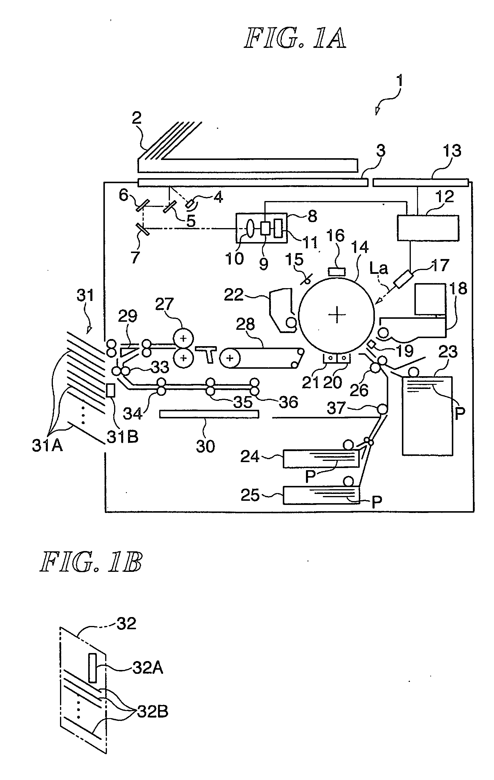
[0058]FIG. 1A is a view schematically showing the construction of an image forming apparatus according to the first embodiment of the present invention provided with a staple sorter. FIG. 1B is a view schematically showing the construction of the image forming apparatus according to the first embodiment of the present invention provided with a bookbinding machine.

[0059] In FIG. 1, an image forming apparatus (copier) 1 has an automatic original feeding device 2, a CCD unit 8, a controller section 12, a photosensitive drum 14, a primary charger 16, a laser unit 17, a developing device 18, a transfer precharger 19, a transfer charger 20, a separating charger 21, a fixing unit 27, a staple sorter 31 (or a bookbinding machine 32), for example.

[0060] The automatic original feeding device 2 sequentially feeds originals to be read (not shown) to a predetermined position on an original platen glass 3 and ejects the original...

second embodiment

[0125] Next, a description will be given of the present invention.

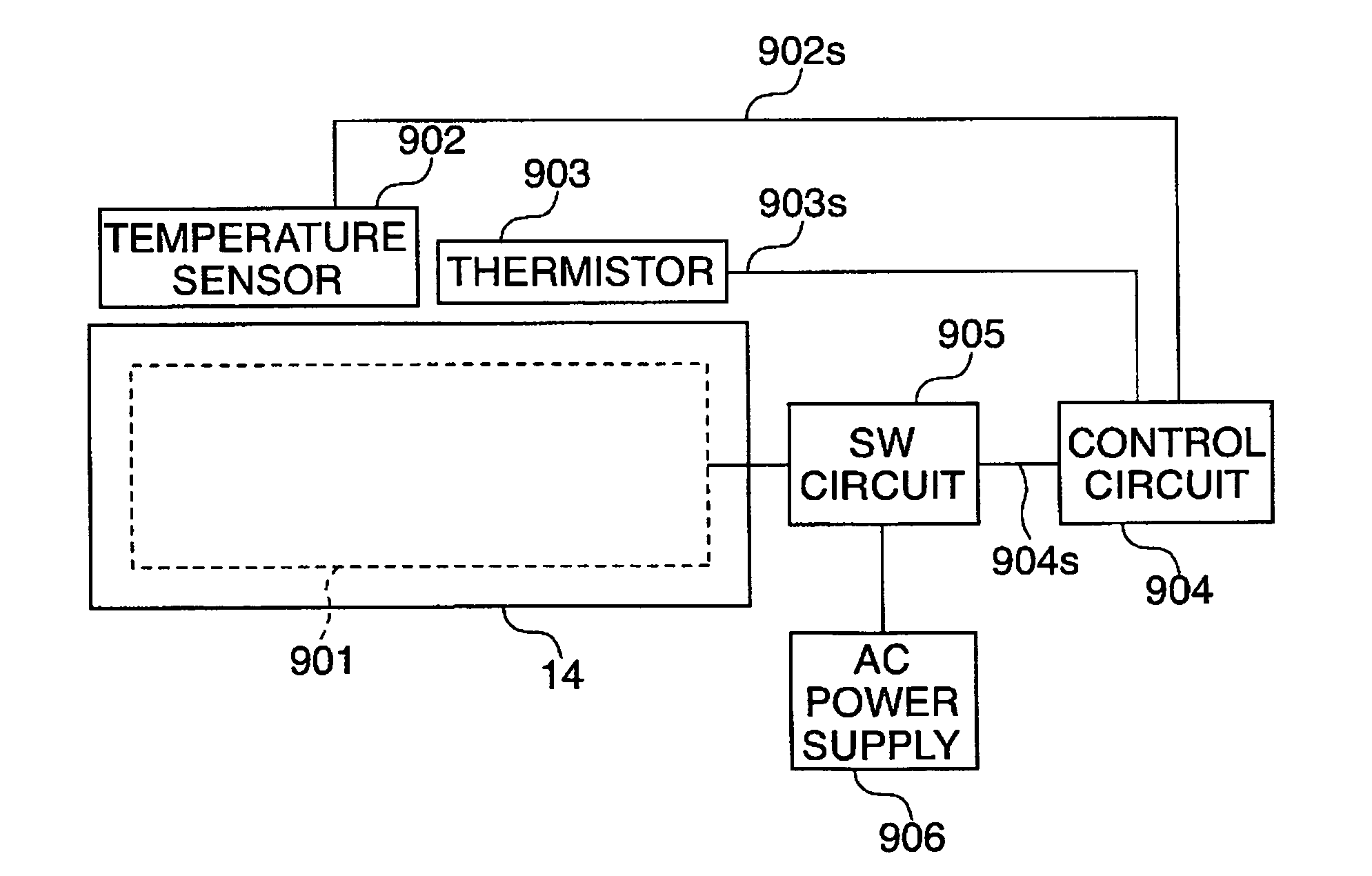
[0126] The second embodiment of the present invention differs from the first embodiment described above in that a non-contact thermistor 903 is not used as a limiter but used for correction of the temperature detected by a thermopile temperature sensor 902 and that a control circuit 904 has an arrangement shown in FIG. 10. The remaining components according to this embodiment are the same as the corresponding components according to the first embodiment described above (FIGS. 1 to 6), and hence descriptions thereof will be omitted.

[0127] Now, an arrangement of the control circuit 904 of the photosensitive drum temperature control system according to this embodiment will be described with reference to FIG. 10.

[0128]FIG. 10 is a block diagram showing an arrangement of the control circuit of the photosensitive drum temperature control system of the image forming apparatus according to the second embodiment of the prese...


PUM


Abstract

An image forming apparatus that can maintain the accuracy of temperature control of an object to be heated within a predetermined range and avoid adverse effects of contamination of first temperature detection means. The image forming apparatus 1 has a photosensitive drum 14, a heater 901, a thermopile temperature sensor 902, a non-contact thermistor 903, and a control circuit 904. The control circuit 904 controls the heater 901 based on an output signal 902s in a case where the output signal 902s is output earlier in time than the output signal 903s, and informs of a state of the thermopile temperature sensor 902 in a case where the output signal 903s is output earlier in time than the output signal 902s.

Description

BACKGROUND OF THE INVENTION [0001] 1. Field of the Invention [0002] The present invention relates to an image forming apparatus that detects and controls the temperature of an object being heated by heating means. For example, it relates to an image forming apparatus that performs temperature control of a photosensitive member and a fixing unit. [0003] 2. Description of the Related Art [0004] A typical image forming apparatus, such as a copier and a printer, uses a laser beam to form an electrostatic latent image on a photosensitive drum, which is an electrostatic latent image carrier. Such an apparatus makes the surface of the photosensitive drum electrified using an electrostatic charger and then sequentially performs exposure, development, transfer and fixing, thereby forming an image on a sheet of paper. [0005] It is known that, in such an image forming apparatus, an ozone product is deposited on the surface of the photosensitive drum, and particularly in a high-humidity environ...

Claims


Application Information

Patent Timeline
IPC IPC(8): G03G15/00
CPCG03G15/2039
Inventor TAMAOKI, TOMOHIRO
Owner CANON KK
Why Eureka
Try Eureka