Fixturing device for drilling workpieces

a fixation device and workpiece technology, applied in the field of apparatus for fixation workpieces, can solve the problems of slipping of drill bits, marring, misaligning or scratching of plated or painted surfaces, etc., and achieve the effects of simple use, convenient maintenance, and convenient manufactur

Inactive Publication Date: 2006-10-19
HERRICK RICHARD
View PDF20 Cites 45 Cited by
  • Summary
  • Abstract
  • Description
  • Claims
  • Application Information

AI Technical Summary

Benefits of technology

[0007] It is accordingly an object of the invention to provide a drilling fixture which overcomes the above-mentioned disadvantages of the heretofore-known devices of this general type and which provides a drilling fixture that is accurate, easily manufactured, easy to maintain, quick and simply to use, has a great deal of versatility, and is reliable.
[0008] The present invention has the advantages that it is not restricted to just two holes at any center distance, it can be a multitude of hole locations and center distances. It securely clamps or locates over a specific hole location and because of its construction, it will not allow a drill bit to slip, mar, misalign or scratch plated or painted surfaces. This is especially important on painted or other finished workpieces. The present invention has the capability of drilling multiple work pieces exactly alike.
[0009] The simplicity of the present invention allows anyone with various skill levels to successfully use the drilling fixture. It is very lightweight and extremely portable.
[0011] The present invention is convenient to use for the following applications: for locating holes to be drilled in round bars and dowel tubes; accurate drilling of bar stock (round, square, hex or rectangular) perpendicularly or at other angles; drilling, with a high level of accuracy, a hole in the end of any length work piece (dowels etc.); drilling out a broken screw in an existing hole; and accurately drilling a hole through the corner of a square bar tube or angle iron.
[0013] The present invention will adapt to any shape work piece (i.e. square, rectangular, round, hex or elliptical). It also has a very unique feature that allows a user to drill any size through hole or blind hole in a circular helical pattern of infinite center distances and angular positions which could conceivably produce a work piece that would have a spiraling pattern for whatever length desired (such as a barber pole pattern).

Problems solved by technology

It securely clamps or locates over a specific hole location and because of its construction, it will not allow a drill bit to slip, mar, misalign or scratch plated or painted surfaces.

Method used


Image

  • Fixturing device for drilling workpieces
  • Fixturing device for drilling workpieces
  • Fixturing device for drilling workpieces

Examples


Embodiment Construction

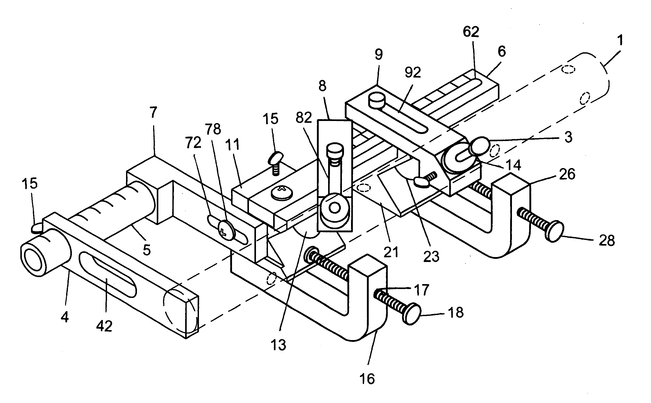
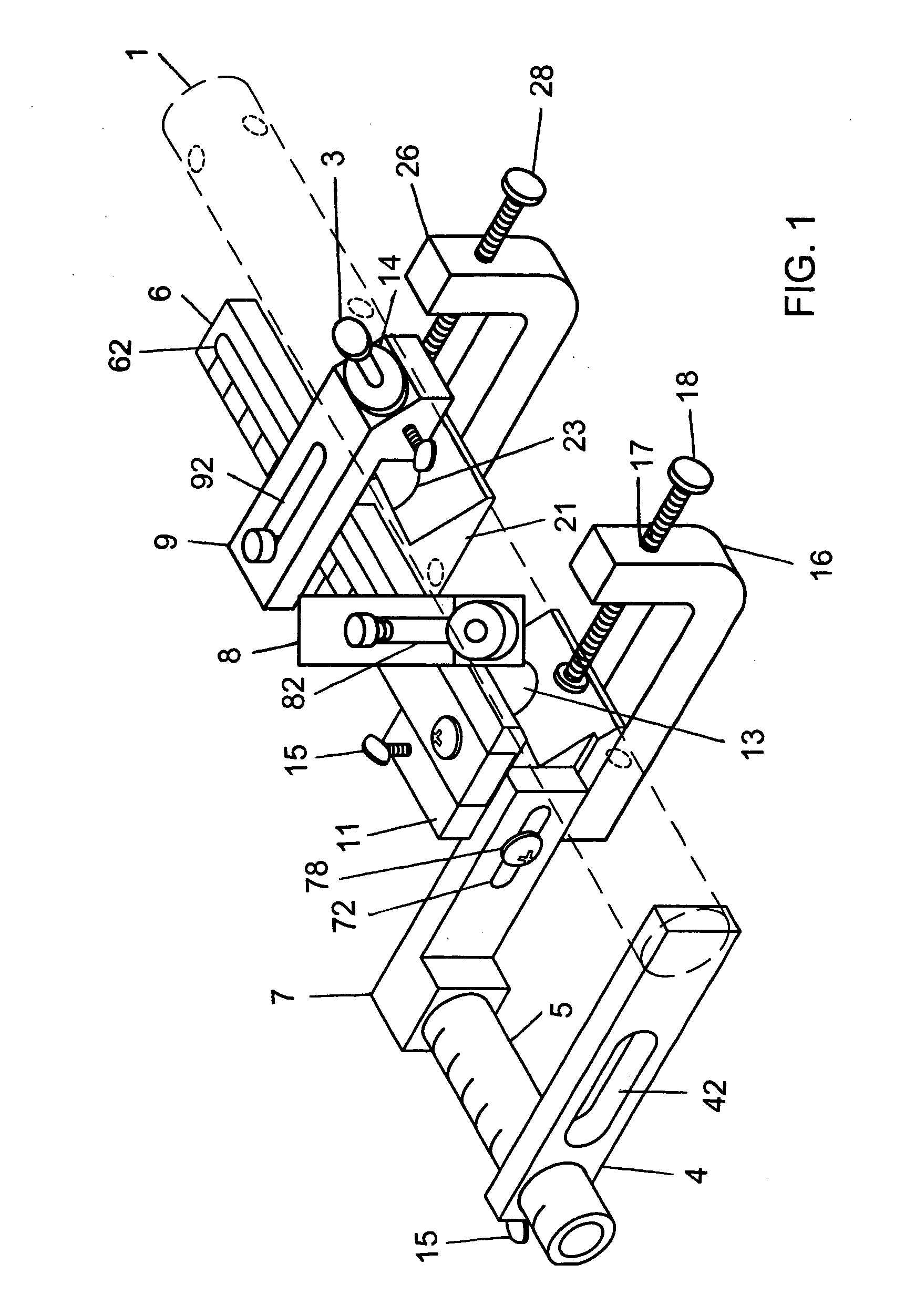
[0040] Referring now to the figures of the drawing in detail and first, particularly, to FIG. 1 thereof, there is seen a drilling fixture according to the invention. The drilling fixture allows for the accurate drilling of differently aligned holes in a workpiece.

[0041] The drilling fixture includes a first v-block 11 and a second v-block 21, which are attached to each other by a mounting cross-member bar 6. The v-blocks 11 and 21 each have respective holding or locating surfaces 114 and 124 that support the workpiece when it is being drilled. It is noted that while the angle between the holding surfaces 114 and 124 of the v-blocks 11 and 21 is illustrated as being 90° it is not necessary that the angle between the holding surfaces 114 and 124 of the v-blocks 11 and 21 be 90°. The angle can be adjusted for the types of workpieces to be handled by the drilling fixture. The holding surfaces 114 and 124 intersect each other and form a v-shape. Transverse axes of the v-blocks 11 and 21...


PUM

PropertyMeasurementUnit
angleaaaaaaaaaa
angleaaaaaaaaaa
sizesaaaaaaaaaa

Abstract

A fixturing device for holding a workpiece with a longitudinal axis is disclosed. The fixturing device includes a first v-block with holding surfaces that intersect each other at an intersection and form a v-shape. The first v-block has a hole formed therein with a center axis that is substantially perpendicular to the longitudinal axis of the workpiece and intersects the intersection of the holding surfaces. A clamping arm mounted to the first v-block for clamping the workpiece in the first v-block. A second v-block that is similar to the first v-block is also provided. A clamping arm is mounted to the second v-block for clamping the workpiece to the second v-block. A cross-member adjustably attaches the first v-block to the second v-block. At least one drill bushing is removably disposed in one of the hole in the first v-block and the hole in the second v-block.

Description

BACKGROUND OF THE INVENTION [0001] 1. Field of the Invention [0002] The invention relates to an apparatus for fixturing workpieces that are to be drilled, more specifically, to a drilling fixture that can be used for the precision drilling of holes in workpieces of different shapes and sizes. [0003] 2. Description of the Related Art [0004] It is prior-art practice, for example, in the case of drilling holes in workpieces to use a hand drill with a center punch for marking the location to be drilled. This practice has the disadvantage that the drill bit can walk on the workpiece thereby causing a marring of the workpiece or causing the hole to be drilled at an improper location. Also, there is the disadvantage that since the drill bit is not oriented or guided with respect to the workpiece the drilled hole will not be drilled at the proper angle with respect to the axis, plane, surface, or diameter of the workpiece. [0005] In order to deal with these problems it is known from the pri...

Claims


Application Information

Patent Timeline
Patent Type & Authority Applications(United States)
IPC IPC(8): B23B47/28
CPCB23B47/28B23B47/281Y10T408/567B23B47/288B23B47/287
Inventor HERRICK, RICHARD
Owner HERRICK RICHARD
Why Eureka
Try Eureka