Microfluidic apparatus having a vaporizer and method of using same

Inactive Publication Date: 2006-10-19
FLUIDIGM CORP
View PDF2 Cites 75 Cited by
  • Summary
  • Abstract
  • Description
  • Claims
  • Application Information

AI Technical Summary

Benefits of technology

[0047] The vaporous environment may be a sealed environment. Moreover, the vapour may be water vapour, especially for protein crystallisation, in which case the level of saturation is preferably in the range of 90-100% RH, more preferably 95-100% RH. For protein crystallisation, it may be conve

Problems solved by technology

Thus, while it will typically only take a few hours for a fast diffusing reagent to diffuse to the protein well, it will typically take the protein days or weeks to diffuse to the reagent well (and vice-versa for slow dif

Method used


Image

  • Microfluidic apparatus having a vaporizer and method of using same
  • Microfluidic apparatus having a vaporizer and method of using same
  • Microfluidic apparatus having a vaporizer and method of using same

Examples


Embodiment Construction

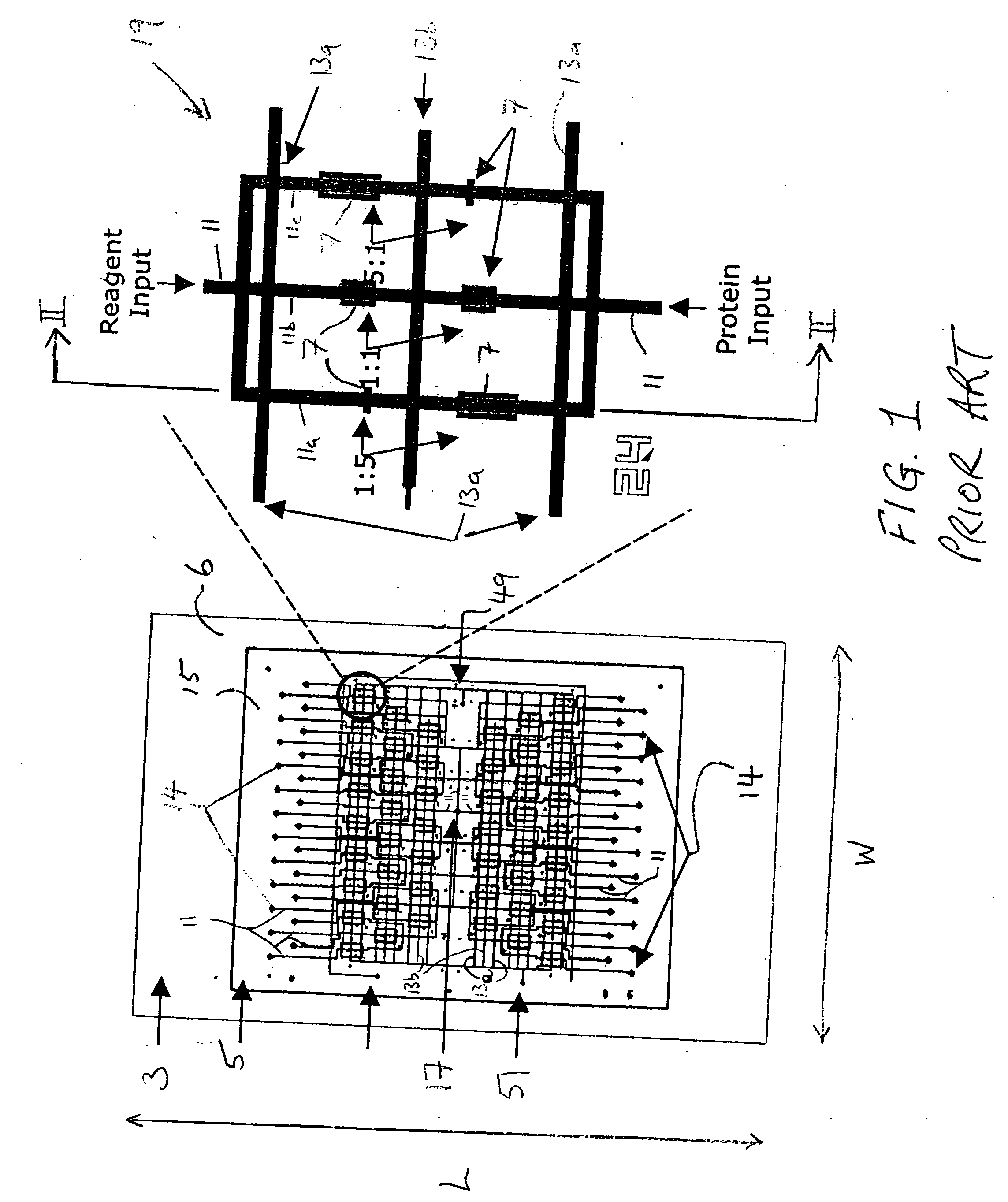
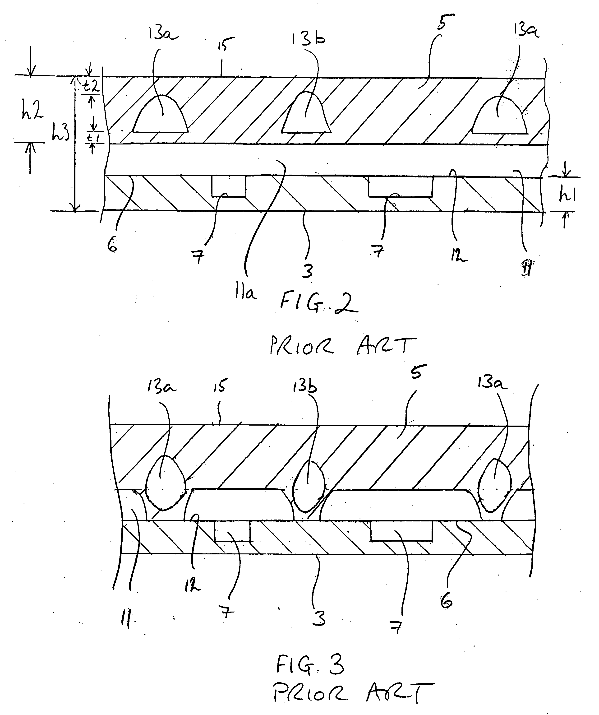
[0065] In FIGS. 1A to 3A there is shown a prior art, transparent protein crystallisation microfluidic chip 1 which is available from Fluidigm Corporation (7100 Shoreline Court, South San Francisco, Calif. 94080, U.S.A.) as part of the Topaz™ system, as detailed previously herein. The chip 1 has a glass base layer 3 on which is mounted an upper layer 5 formed from the elastomer polydimethyl siloxane (PDMS).

[0066] The glass layer has a length L of about 74-75 mm, a width W of about 50 mm and a height h1 of about 1 mm. An upper surface 6 of the glass layer 3 is provided with an orderly array of two hundred and eighty eight wells 7 therein (microwells). As evident from FIG. 1B, the volumes of the individual wells 7 vary.

[0067] The upper layer 5 is formed by the MSL™ technique, details of which are to be found on inter alia Fluidigm's website supra, and, as will be understood from FIGS. 1 and 2, has a set of microfluidic supply conduits 11 formed in a lower surface 12 thereof and a set...


PUM


Abstract

An apparatus for performing microchemistry having:—
  • (a) a vapour permeable microfluidic chip structure (1) having:—
    • a supply conduit (11a-c) enclosed in the chip structure having first and second opposed ends to enable first and second fluid materials to interact by flowing the first and second fluid materials towards one another from the opposed ends of the supply conduit, and
    • a valve mechanism (13b) in the chip structure operable to open and close the supply conduit at an intermediate position (55) located between the first and second ends thereof whereby the chip structure is sequentially movable from a filling state in which the intermediate position is closed to enable the fluid materials to be blind-filled in the supply conduit on opposed sides of the intermediate position and an interaction state in which the intermediate position is open to enable the fluid materials to interact; and
  • (b) a vaporizer (100) for forming a vaporous environment about the chip structure to compensate for evaporation of the fluid materials from the supply conduit of the chip structure in the interaction state.

Description

RELATED APPLICATION [0001] The present patent application claims priority from UK patent application No. 0302302.5 filed on 31 Jan. 2003, the entire content of which is hereby incorporated herein by reference. FIELD OF THE INVENTION [0002] The present invention relates to a microfluidic apparatus and method and is particularly, but not exclusively, concerned with improvements in protein crystallisation in a microfluidic chip. BACKGROUND OF THE INVENTION [0003] A microfluidic chip for performing protein crystallisation has been developed by Fluidigm Corporation (www.fluidigm.com) as part of the Topaz™ system. This chip is discussed in the paper ‘A Robust and Scalable Microfluidic Metering Method that allows Protein Crystal Growth by Free Interface Diffusion’. Hansen et al. Proceedings of the National Academy of Sciences of the United States (PNAS), Vol. 99, No. 26, 2002, p. 16531-16536. [0004] This microfluidic chip is fabricated by a technique referred to as “Multi-Layer Soft Lithog...

Claims


Application Information

Patent Timeline
IPC IPC(8): B01L3/00
CPCB01L3/502707B01L3/502723B01L3/502738B01L2200/0689B01L2200/142B01L2400/0655B01L2300/0887B01L2300/10B01L2300/123B01L2400/0481B01L2300/0816
Inventor NELSON, JAMES CURTIS
Owner FLUIDIGM CORP
Why Eureka
Try Eureka