Intravascular deployment device with improved deployment capability

Active Publication Date: 2006-10-19
MEDTRONIC VASCULAR INC
View PDF24 Cites 59 Cited by
  • Summary
  • Abstract
  • Description
  • Claims
  • Application Information

AI Technical Summary

Benefits of technology

[0012] In another aspect, the variable stiffness member includes at least a low stiffness portion having a stiffness which is less stiff, or less resistant to bending, than is the compressed stent graft held in the graft cover. As a result, when the stent graft is being introduced over the guidewire through tortuous anatomy, buckling will more likely occur at the location of greatest bending or flexing of the graft cover, which location will occur along a least stiff portion of the stent graft/variable stiffness member combination, which is located at the proximal end of the stent stop and thus in a location where the buckle in the graft cover will not create an interference fit with the stent stop and ther

Problems solved by technology

One issue which may arise during deployment of the stent graft from the graft cover, and which has serious consequences, is that the graft cover may become bound up with the stent stop, such that the graft cover cannot be retracted or moved relative to the stent stop.
One cause of this binding is buckling of the graft cover, which can occur when the graft cover and middl

Method used


Image

  • Intravascular deployment device with improved deployment capability
  • Intravascular deployment device with improved deployment capability
  • Intravascular deployment device with improved deployment capability

Examples


Embodiment Construction

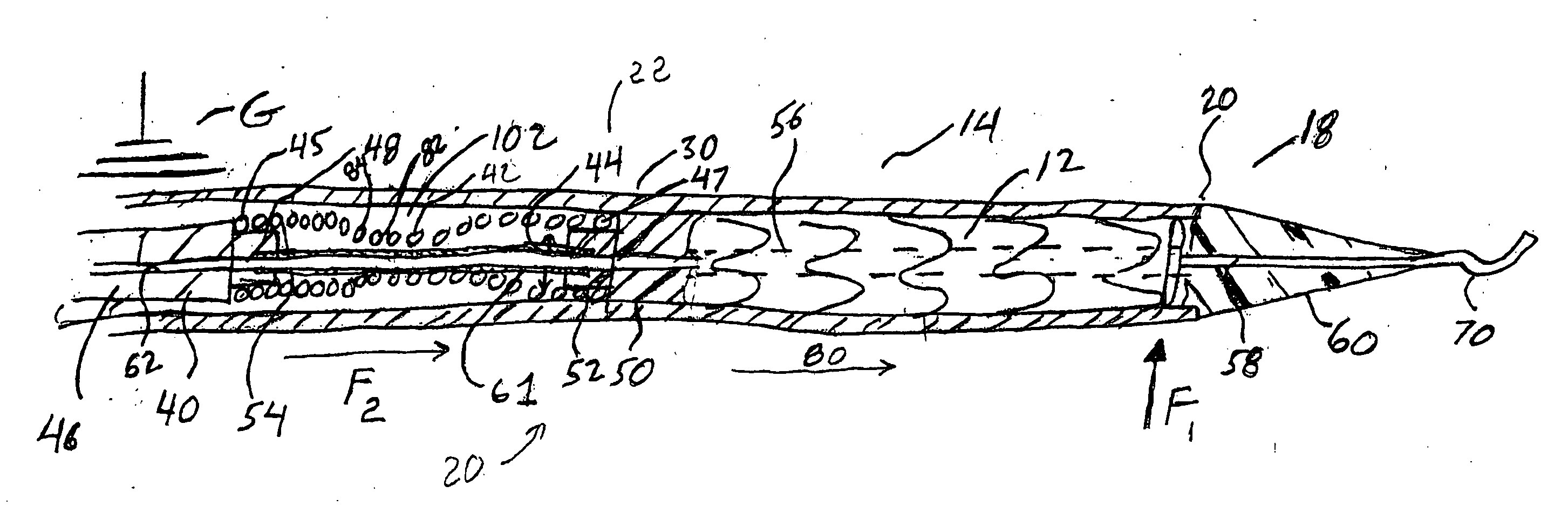
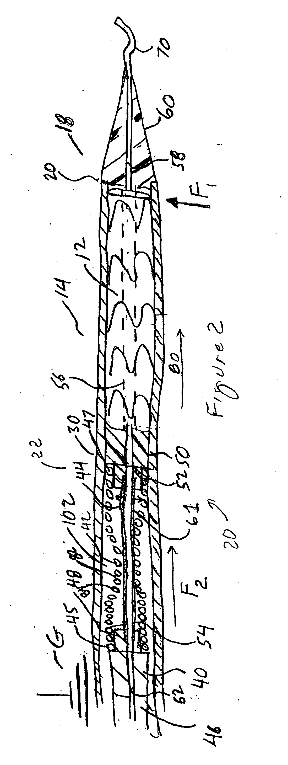
[0033] Method and apparatus are provided for the delivery of exclusion devices, such as stent grafts, to aneurysmal sites in a patient, wherein the effect of buckling of the outer tubular sheath, or graft cover, of the delivery device, on the ability to deploy the stent graft therefrom is mitigated.

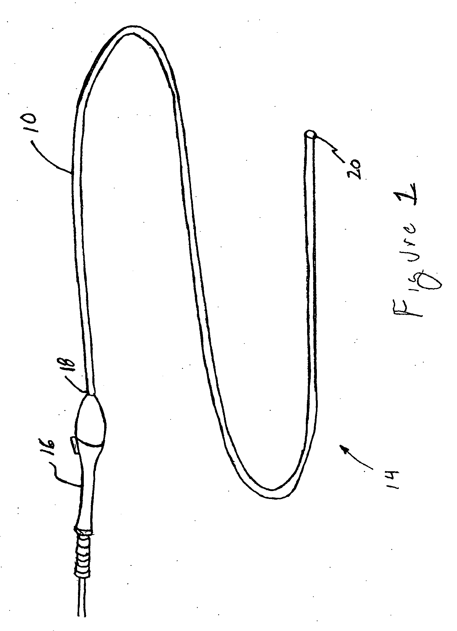
[0034] Referring initially to FIG. 1, there is shown a delivery system 10 according to the present invention, which generally includes: a tubular delivery catheter 14, terminating at a distal end 20; an operator 16, disposed adjacent to proximal end 18 of tubular delivery catheter 14 and positioned to enable a surgeon or technician to manipulate the tubular delivery catheter 14 within a flow lumen (not shown) of a patient. Thus, in use, the tubular delivery catheter is tracked in an artery (not shown) of a patient, to position the distal end 20 thereof at a position, in a blood flow direction, upstream of the aneurysm (not shown), wherein an exclusion device may be deployed across the an...


PUM


Abstract

An intravascular delivery catheter includes a middle member or manipulator to ameliorate the effect of buckling of the graft cover during the tracking or positioning of the delivery device within a body flow lumen to deploy an exclusion device, such a stent graft. The delivery device/catheter includes a region or regions of lower resistance to bending than other portions of the delivery device, which are positioned, within the delivery device, to preferentially bend the delivery system at locations where buckling will have minimal effect upon the deployment of the exclusion device from the delivery system. The preferential bending is accomplished, by providing a middle member/manipulator that is a rod with laterally oriented slots, having different depth and spacing configurations, or by using a wire coil as a portion of the middle member where the variable stiffness is created either by providing a variable/multiple coil diameter or by using a wire having a variable diameter along its length while the wire coil diameter is relatively uniform.

Description

BACKGROUND OF THE INVENTION [0001] 1. Field of the Invention [0002] The present invention relates to the field of intravascular deployment systems. More particularly, the invention relates to the field of apparatus and methods for the deployment of intravascular devices, including exclusion devices such as stent grafts, where interference between the components of the delivery apparatus may lead to an inability to deploy the device or result in partial deployment of the device. [0003] 1. Background of the Art [0004] Intravascular deployment of exclusion devices (stent grafts) is a methodology used to deliver an exclusion device to a portion of a body flow lumen that is diseased or damaged, such as an aneurysmal portion of an aorta, and, thence deploy the exclusion device to span the diseased or damaged portion of the aorta and thereby provide a synthetic flow conduit which passes through the diseased or damaged portion of the aorta and seals against healthy tissue of the aorta at lo...

Claims


Application Information

Patent Timeline
IPC IPC(8): A61F2/06
CPCA61F2/95A61F2250/0039A61F2250/0018A61F2/966
Inventor BELLUCHE, TERRANCE D.DOIG, SCOTTHUSZAR, HILLARY K.KIM, ANDREWMEIER, STEPHEN CLARK
Owner MEDTRONIC VASCULAR INC
Why Eureka
Try Eureka