Intervertebral disc prosthesis with a motion- adapted edge for the lumbar and cervical spine

Active Publication Date: 2006-10-19
BUETTNER JANZ KARIN +1
View PDF32 Cites 118 Cited by
  • Summary
  • Abstract
  • Description
  • Claims
  • Application Information

AI Technical Summary

Benefits of technology

[0073] In a further design of a three part intervertebral disc prosthesis it is intended that the height of the middle sliding partner partly or totally continuously increases beginning from the transition area between the convexity and the edge up unto the peripheral edge area. This is intended without the size of the aperture angle changing as a result of an adaptation to the height of the edge of the upper and lower sliding partner. This “dovetail” shape of the edge of the middle sliding partner increases the safeguard against dislocation.
[0074] As per invention, a shape for the upper and lower sliding partner is intended for a three-part prosthesis, in which the periph

Problems solved by technology

It results from biomechanical considerations, unsatisfactory results of fusion surgeries, disorders adjacent to fusion segments and from the development of new materials with greater longevity.
As result of these osteophytes and also by a pathologic course of motion of the intervertebral disc alone, the irritation of neural structures is possible.
However during surgery there is more surgical effort and the risk to damage the vertebral endplates with the resulting danger of subsidence of the prosthesis into the vertebral bodies, if the prosthesis has to be removed completely, because a good adjustment of lordosis and an optimal load of the center of the polyethylene core were not achieved.
Especially due to a load transfer over too small surface areas, a migration of the endplates

Method used


Image

  • Intervertebral disc prosthesis with a motion- adapted edge for the lumbar and cervical spine
  • Intervertebral disc prosthesis with a motion- adapted edge for the lumbar and cervical spine
  • Intervertebral disc prosthesis with a motion- adapted edge for the lumbar and cervical spine

Examples


Example

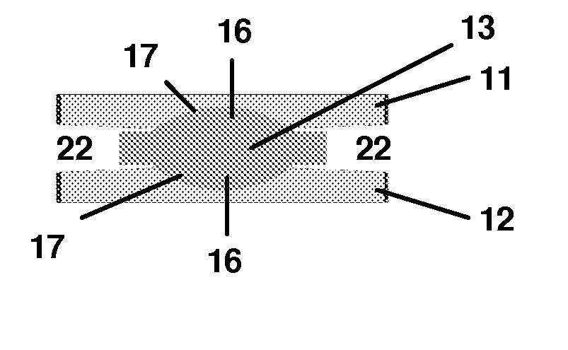
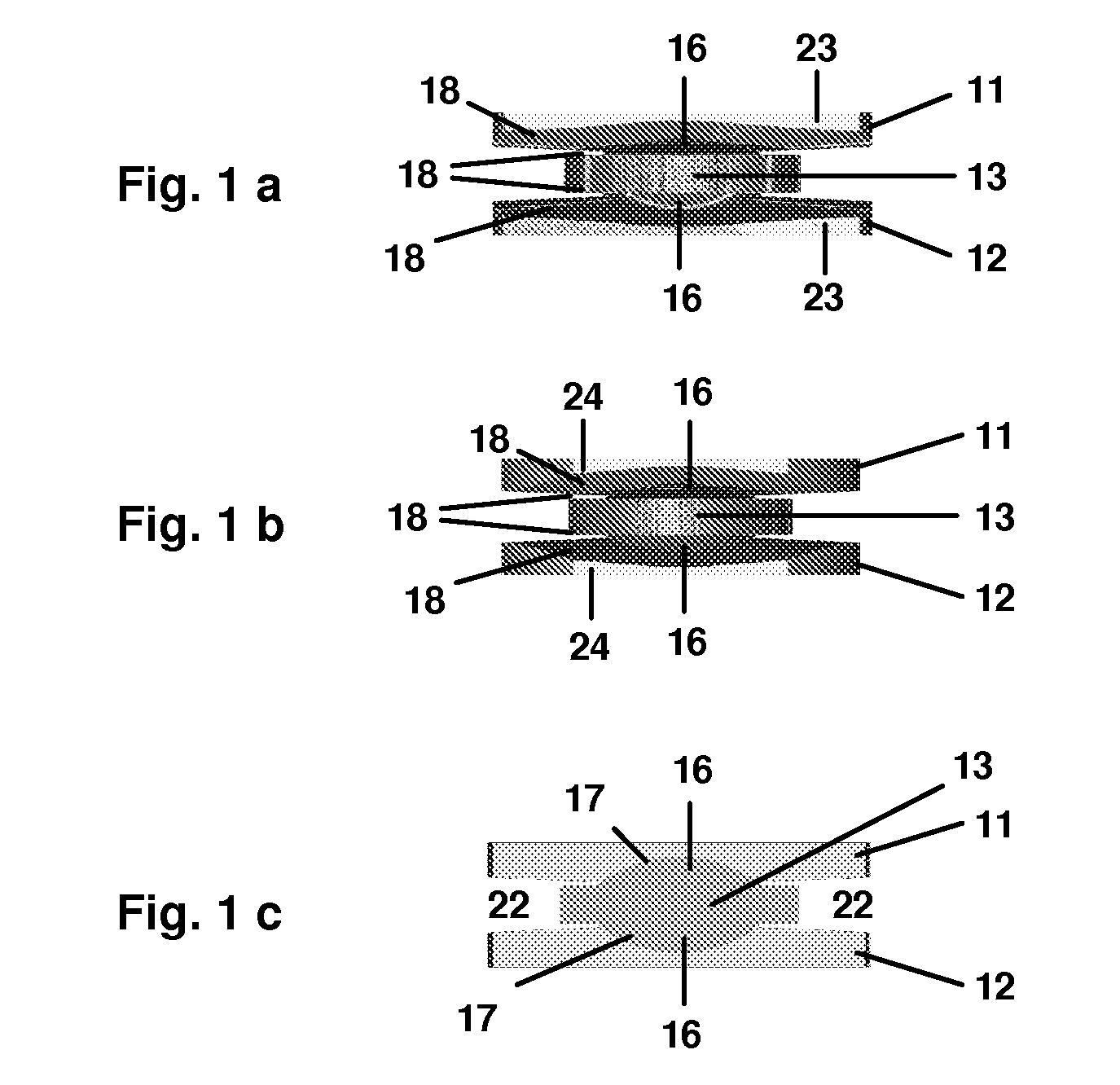
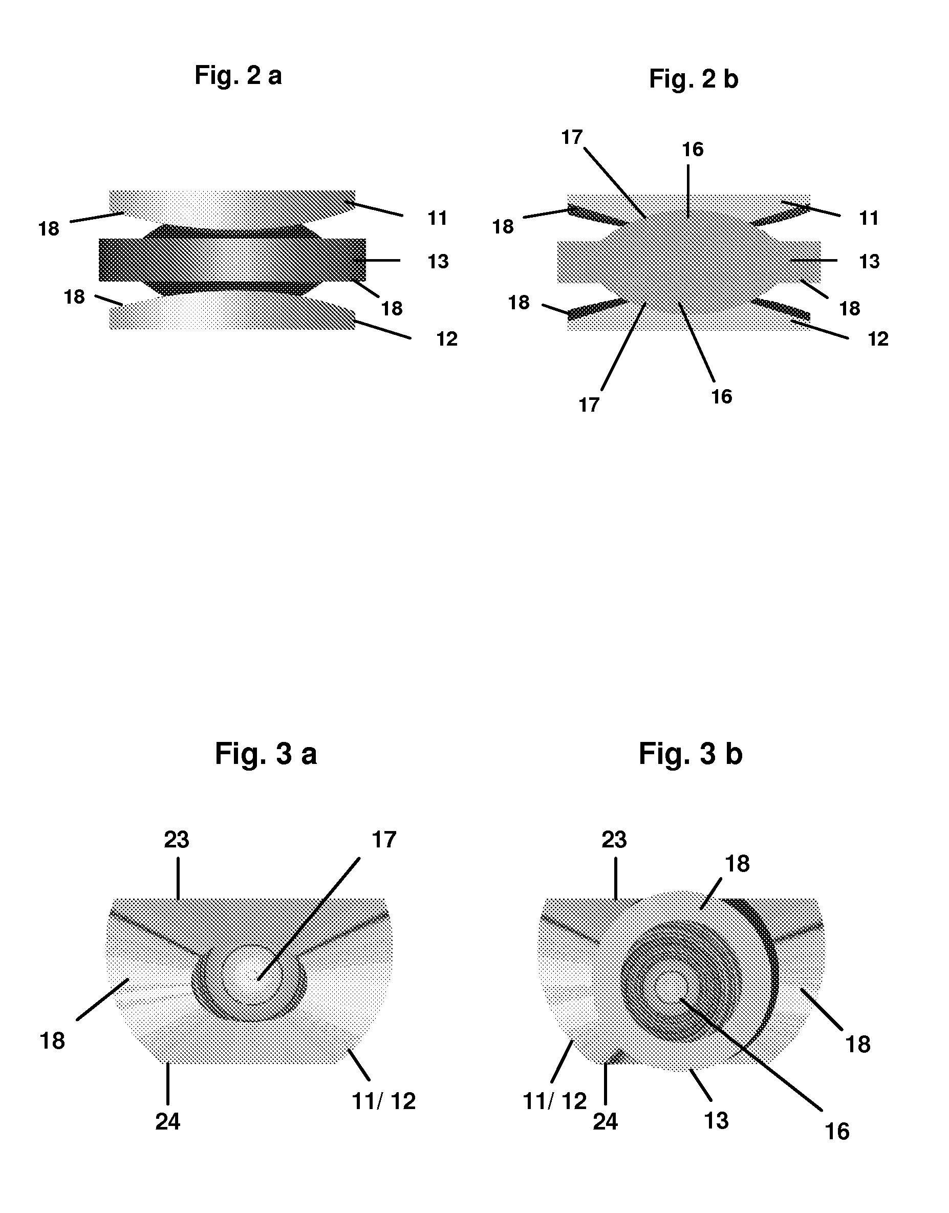
[0098]FIGS. 1a-c show different spatial frontal views of a model of a functional three-part intervertebral disc prosthesis, as per invention, for the lumbar spine, with the middle sliding partner 13 having a edge 18. As per invention, however, other models of a three-part intervertebral disc prosthesis are also planned, where the middle sliding partner 13 is constructed without a edge 18.

[0099]FIG. 1a shows a frontal view of the dorsal side 23 and FIG. 1b of the ventral side 24 of an intervertebral disc prosthesis, as per invention. In an intervertebral disc prosthesis, as per invention, intended for the implantation into the lumbar spine, the ventral side 24 (FIG. 1b) is narrower than the dorsal side 23 (FIG. 1a), as a result of the ventrally tapering off shape of the upper and lower sliding partner 11, 12. For an implantation of the intervertebral disc into the cervical spine, the external circumference of the upper and lower sliding partner 11, 12 tapers off dorsally.

[0100] In ...


PUM


Abstract

The invention relates to an intervertebral disc prosthesis for the total replacement of the intervertebral disc within the lumbar and cervical spine. For a two part as well as for a three part intervertebral disc prosthesis, according to the invention, in accordance to the design of the edges of the sliding partners, there are aspects for at least one of the sliding partners, in which there is an wavelike design of the edge, as the respectively differently high edge regions preferably fluently merge. A significant advantage of the two intervertebral disc prostheses, according to the invention, compared to the present state of the art of already known prostheses, is that as a result of a central transfer of load across a large surface area due to the spherical sliding surfaces, the maximally possible inclination of the sliding partners towards each other in a dorsoventral and laterolateral direction and/or the extent of rotation can, according to the invention, be defined through the wavelike design of the edge region.

Description

CROSS REFERENCE SECTION [0001] This is a continuation-in-part application of international application no. PCT / DE2005 / 001885, filed Oct. 18, 2005 designating the U.S. and claiming priority to international application no. PCT / DE2004 / 002332, filed Oct. 18, 2004. Both of these applications are incorporated herein by reference in their entirety.FIELD OF THE INVENTION [0002] The invention relates to an intervertebral disc prosthesis for the total replacement of an intervertebral disc of the lumbar and cervical spine. BACKGROUND OF THE INVENTION [0003] The idea of function-retaining artificial replacements for intervertebral discs is younger than that for replacements of artificial joints of extremities, but in the meantime about 50 years old [Büttner-Janz, Hochschuler, McAfee (Eds.): The Artificial Disc. Springer Verlag, Berlin, Heidelberg, New York 2003]. It results from biomechanical considerations, unsatisfactory results of fusion surgeries, disorders adjacent to fusion segments and ...

Claims


Application Information

Patent Timeline
IPC IPC(8): A61F2/44
CPCA61F2/4425A61F2002/30616A61F2002/30663A61F2002/30841A61F2310/00269A61F2310/00023A61F2310/00029A61F2310/00131A61F2002/443
Inventor BUETTNER-JANZ, KARINBUETTNER, EIKO
Owner BUETTNER JANZ KARIN
Why Eureka
Try Eureka