Control of exhaust temperature for after-treatment process in an e-turbo system

Active Publication Date: 2006-10-26
GARRETT TRANSPORATION I INC
View PDF14 Cites 66 Cited by
  • Summary
  • Abstract
  • Description
  • Claims
  • Application Information

AI Technical Summary

Problems solved by technology

On the other hand, when the variable-geometry mechanism position is such that the turbine does not provide enough power to reach the target boost pressure, the electrical motor / generator is operated in a motor mode to input the needed additional power to the turbocharger in order to meet the target boost pressure.

Method used


Image

  • Control of exhaust temperature for after-treatment process in an e-turbo system
  • Control of exhaust temperature for after-treatment process in an e-turbo system
  • Control of exhaust temperature for after-treatment process in an e-turbo system

Examples


Embodiment Construction

[0013] The present inventions now will be described more fully hereinafter with reference to the accompanying drawings, in which some but not all embodiments of the inventions are shown. Indeed, these inventions may be embodied in many different forms and should not be construed as limited to the embodiments set forth herein; rather, these embodiments are provided so that this disclosure will satisfy applicable legal requirements. Like numbers refer to like elements throughout.

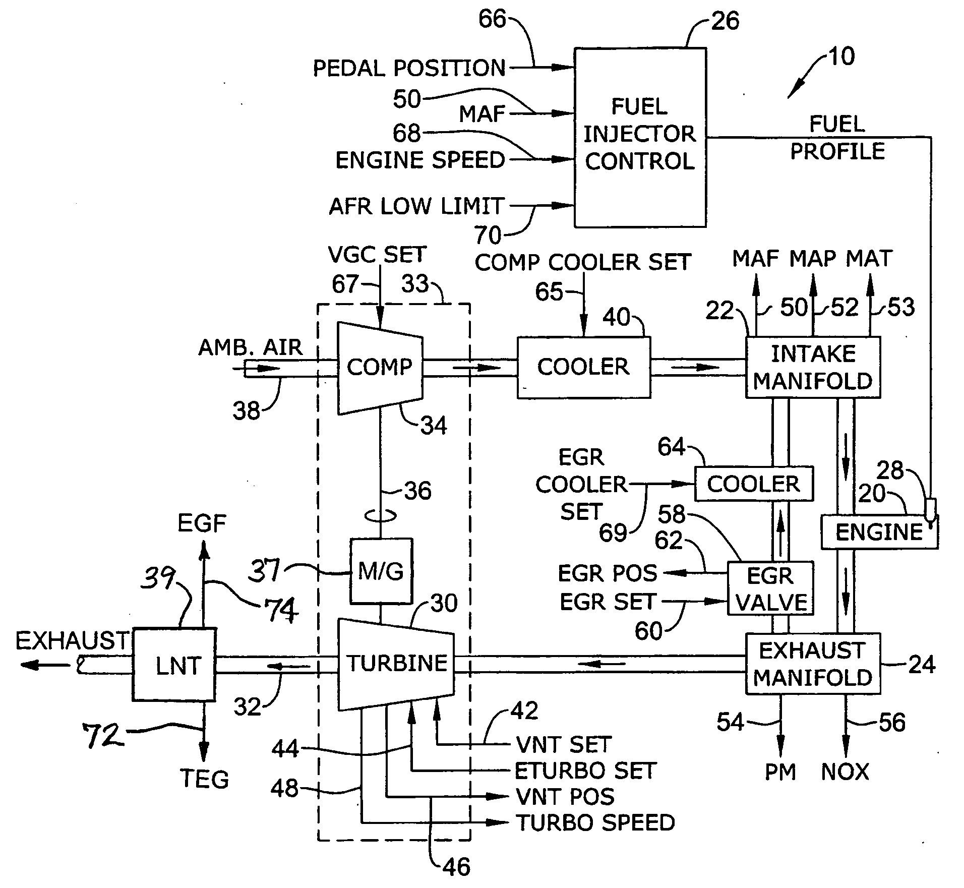
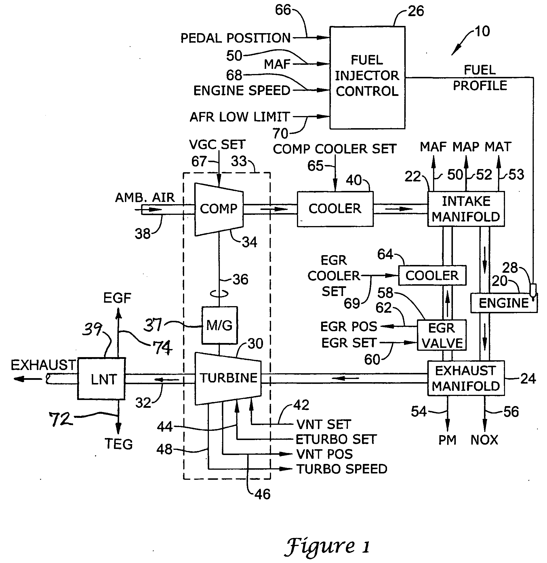
[0014]FIG. 1 is a schematic view of an illustrative internal combustion engine system in accordance with the present invention. The illustrative internal combustion engine system is generally shown at 10, and includes a internal combustion engine 20 that has an intake manifold 22 and an exhaust manifold 24. The internal combustion engine 20 can be a diesel engine, a gasoline engine (e.g., a lean-burn, direct-injection gasoline engine), or the like. In the illustrative embodiment, a fuel injector 28 provides f...


PUM


Abstract

A method for operating a turbocharged internal combustion engine having an after-treatment device for treating exhaust gas discharged from the turbocharger, wherein exhaust gas from the engine is passed through a variable-geometry mechanism for regulating power produced by the turbine. The method comprises the steps of measuring a boost pressure of the air delivered to the intake of the engine, measuring a temperature of the exhaust gas delivered to the after-treatment device, causing the temperature of the exhaust gas delivered to the after-treatment device to substantially match a predetermined target temperature by controlling the variable-geometry mechanism of the turbine to control the amount of power extracted by the turbine, and causing the boost pressure to substantially match a predetermined target boost pressure by either inputting mechanical power into or extracting mechanical power from the turbocharger, as required, using a power addition / extraction device, such as a motor / generator, coupled to the turbocharger.

Description

BACKGROUND OF THE INVENTION [0001] The present invention relates in general to turbocharged internal combustion engine systems, and more particularly relates to systems in which the exhaust gas from the engine is subjected to an after-treatment process for reducing emissions. [0002] Internal combustion engines are often turbocharged for increasing their power and torque output. One commonly employed type of turbocharger for this purpose is a variable-nozzle exhaust gas turbocharger having a turbine that extracts power from the exhaust gas discharged by the internal combustion engine and drives a compressor that compresses air and delivers the air to the engine intake. The turbine includes a variable-geometry mechanism that can be opened or closed by varying degrees for regulating the flow of exhaust gas into the turbine, thereby regulating how much power the turbine extracts. In this manner, the boost pressure of the air supplied to the intake can be regulated in a desired fashion d...

Claims


Application Information

Patent Timeline
Patent Type & Authority Applications(United States)
IPC IPC(8): F01N5/04F02B29/04F02D23/00F02B33/44
CPCF01N3/0807Y02T10/47F01N11/002F01N2430/00F02B37/10F02B37/24F02B39/10F02D23/00F02D41/0007F02D41/0072F02D41/024F02D2041/0075Y02T10/144Y02T10/26F01N3/2006Y02T10/12Y02T10/40
Inventor KOLAVENNU, SOUMITRI N.SHAHED, SYED M.
Owner GARRETT TRANSPORATION I INC
Why Eureka
Try Eureka