

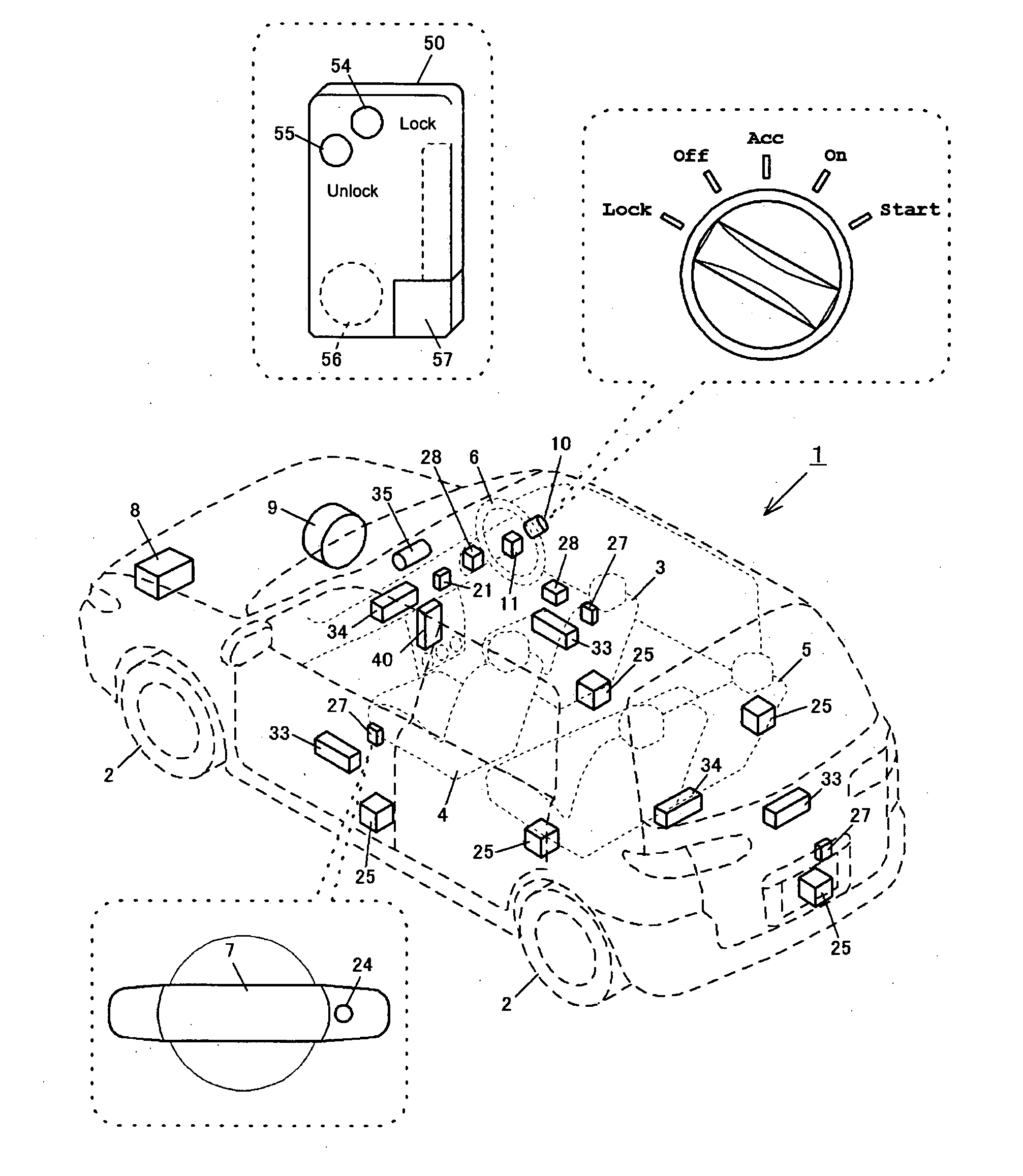
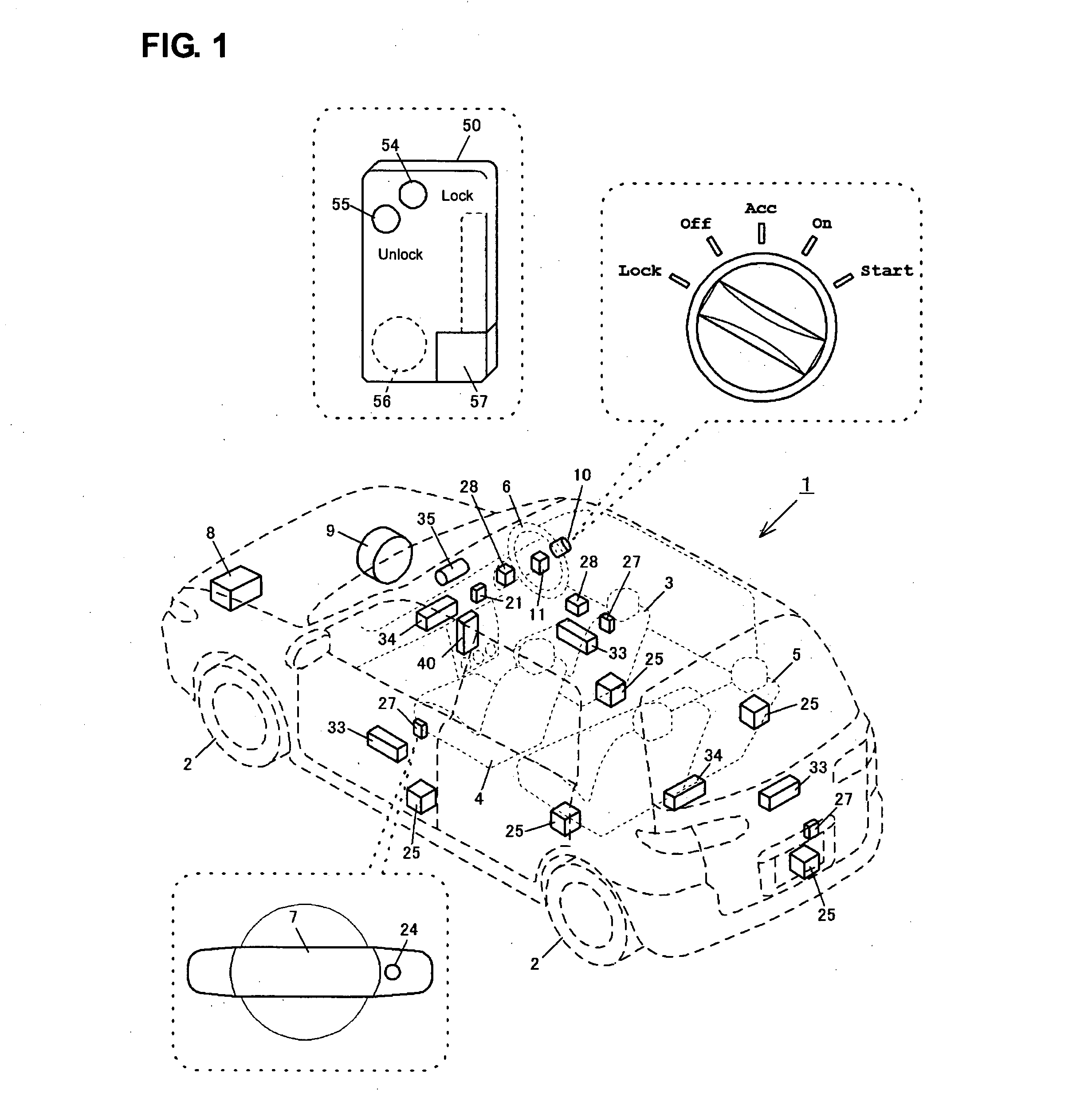
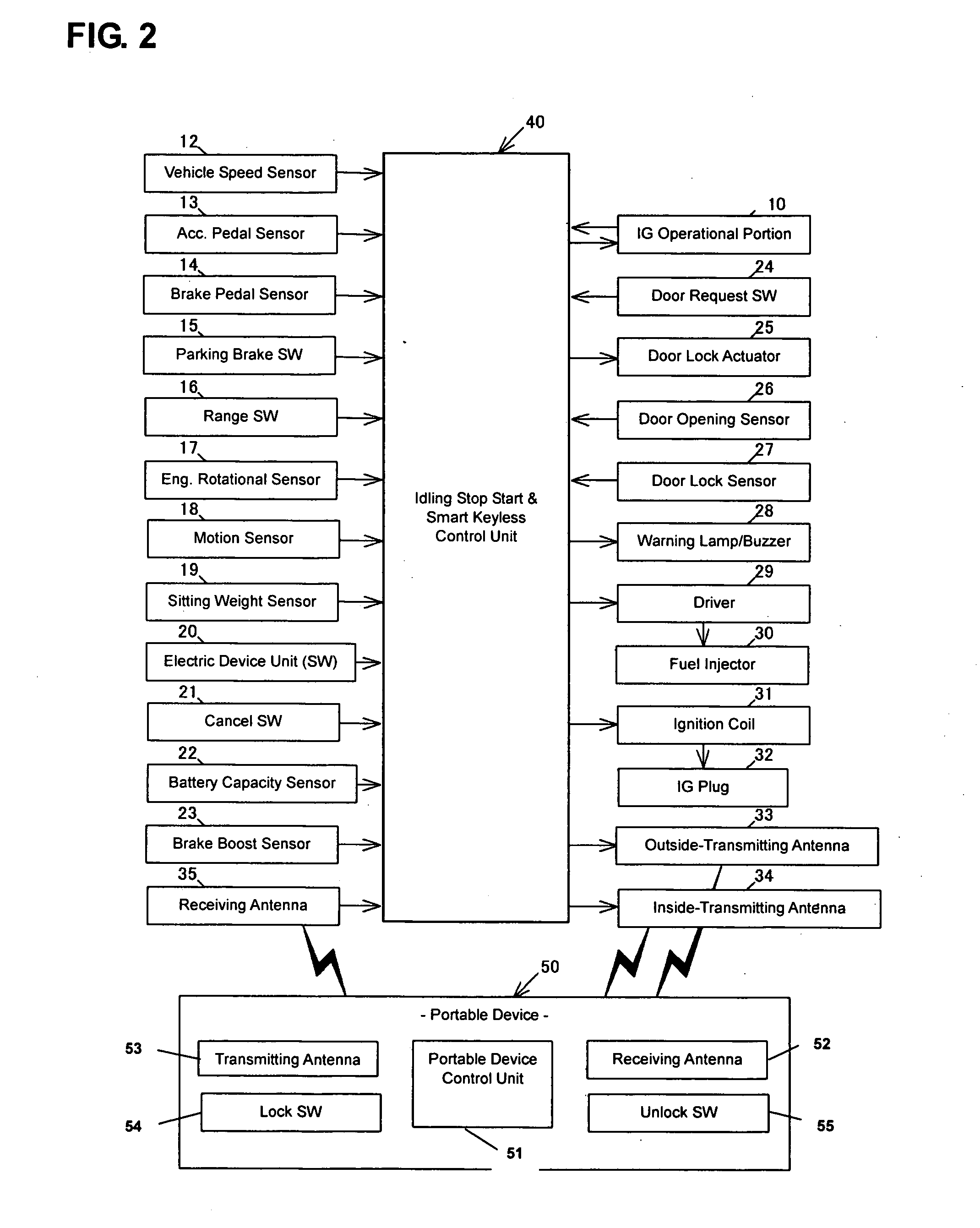
Control system for vehicle
- Summary
- Abstract
- Description
- Claims
- Application Information
AI Technical Summary
Benefits of technology
Problems solved by technology
Method used
Image

Examples
second embodiment
[0071] Next, the idling stop start control routine of the steps S7, S13 in FIG. 7 will be described referring to a flowchart in FIG. 11. As compared with FIGS. 8-10, only a portion that corresponds to FIG. 10 is different from the previous embodiment. Accordingly, this difference will be described below.
[0072] When it is determined that the battery capacity decreases below the first capacity in the step S29 or the brake boost decreases below the first boost in step S30, the intensity of the request signal A is increased and / or the threshold of the ID signal B is decreased in step S140. Namely, a control to enhance a function of the ID verification of the portable device 50 is executed. Then, the request signal A is transmitted in step S141. It is determined in step S103 whether the portable device 50 receives this request signal A or not. When receiving, the portable device 50 transmits the ID signal B including its own ID code in step S104.
[0073] The control unit 40 determines in ...
third embodiment
[0077] Next, the idling stop start control routine will be described referring to flowcharts in FIGS. 12 and 13.
[0078] When the battery capacity decreases below the first capacity in the step S29 or the brake boost decreases below the first boost in the step S30 in FIG. 9, the control sequence proceeds to step S240 in FIG. 12, where the unit 40 determines whether a cancel switch operation is conducted or not. When the cancel switch is not operated, it is determined in step S241 whether the passenger is in the vehicle or not. When the passenger is not, the control unit 40 transmits the request signal A in step S242. The portable device 50 determines in step S103 whether it receives the above-described request signal A or not. When it receives the signal, the portable device 50 transmits the ID signal B including its own code in the step S104.
[0079] Herein, the cancel switch operation in the step S240 is effective for a specified period of time, i.e., until the IG stop operation is c...
PUM
 Abstract
Description
Claims
Application Information