Percussion power tool

a percussion and power tool technology, applied in the field of hammer drills or chisel hammers, can solve the problems of reducing the secondary impact of the percussion piston and the striker is generally stronger than the secondary impact of the power tool with a reduced power, and the kinetic energy of the hammer drill or chisel hammer is reduced, so as to achieve the effect o

Inactive Publication Date: 2006-10-26
HILTI AG
View PDF6 Cites 25 Cited by
  • Summary
  • Abstract
  • Description
  • Claims
  • Application Information

AI Technical Summary

Benefits of technology

[0022] Preferably, the contact point is spaced from the percussion axis by a distance that corresponding to an axial length of the striker times 0.003-0.05. This distance insures an increased friction between the impact element or the striker and a corresponding guide in comparison with friction produced in the percussion mechanism with a central impact of the impact element on the striker, and the increased friction reduces the kinetic energy. A distance corresponding to an axial length of the striker times 0.005-0.03 proved to be particularly advantageous for achieving an optimal relationship between the obtained reduction of the kinetic energy, impairment to pulse transmission, and wear of the guides.

Problems solved by technology

The drawback of the German reference DE 31 21 616 A1 consists in that in case of a breakdown of the working tool in the construction component or when the working tool is lifted off the constructional component, both the percussion piston and the striker are subjected to secondary impacts.
Hammer drills or chisel hammers having an increased power are generally subjected to stronger secondary impacts that the power tools with a reduced power.
This, in turn, results in a longer hammer drill or chisel hammer which is highly undesirable for ergonomical reasons, e.g., because of an increased weight and / or difficult handling of such hammer drills or chisel hammers.
As it was explained previously, for constructional and ergonomical reasons, there is no adequate way to reduce the kinetic energy by friction.
When an impact energy of a single blow produced by a hammer drill or chisel hammer is very high, additional and constructively expensive measures such as, e.g., provision of a brake for the striker or of arresting device in the percussion mechanism should be undertaken in order to prevent secondary impacts.
The drawback of this solution consists in a complex construction of such brakes which, e.g., because of their soiling or wear, can easily fail, which noticeably reduce the service life of a hammer drill or chisel hammer.

Method used


Image

  • Percussion power tool
  • Percussion power tool
  • Percussion power tool

Examples


Embodiment Construction

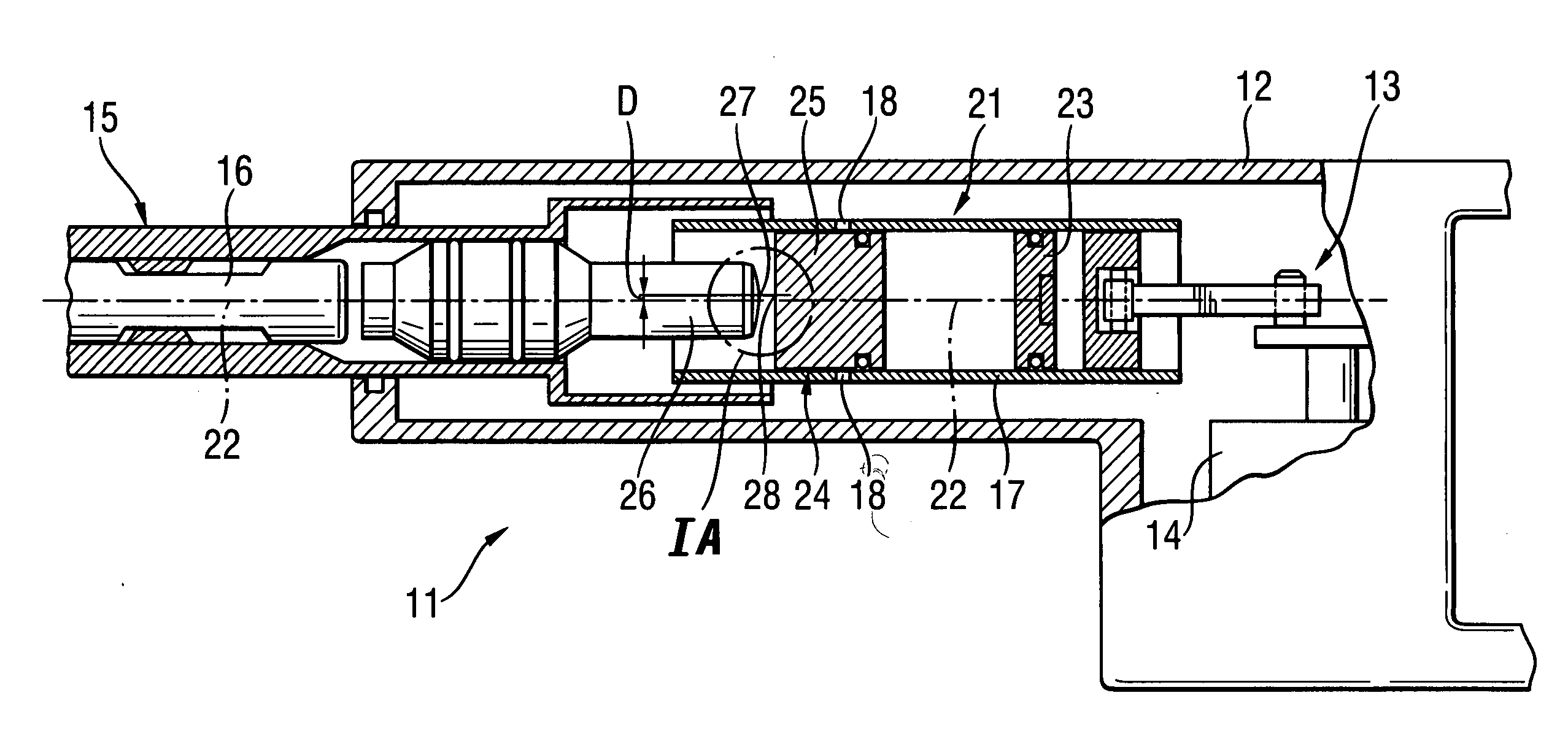
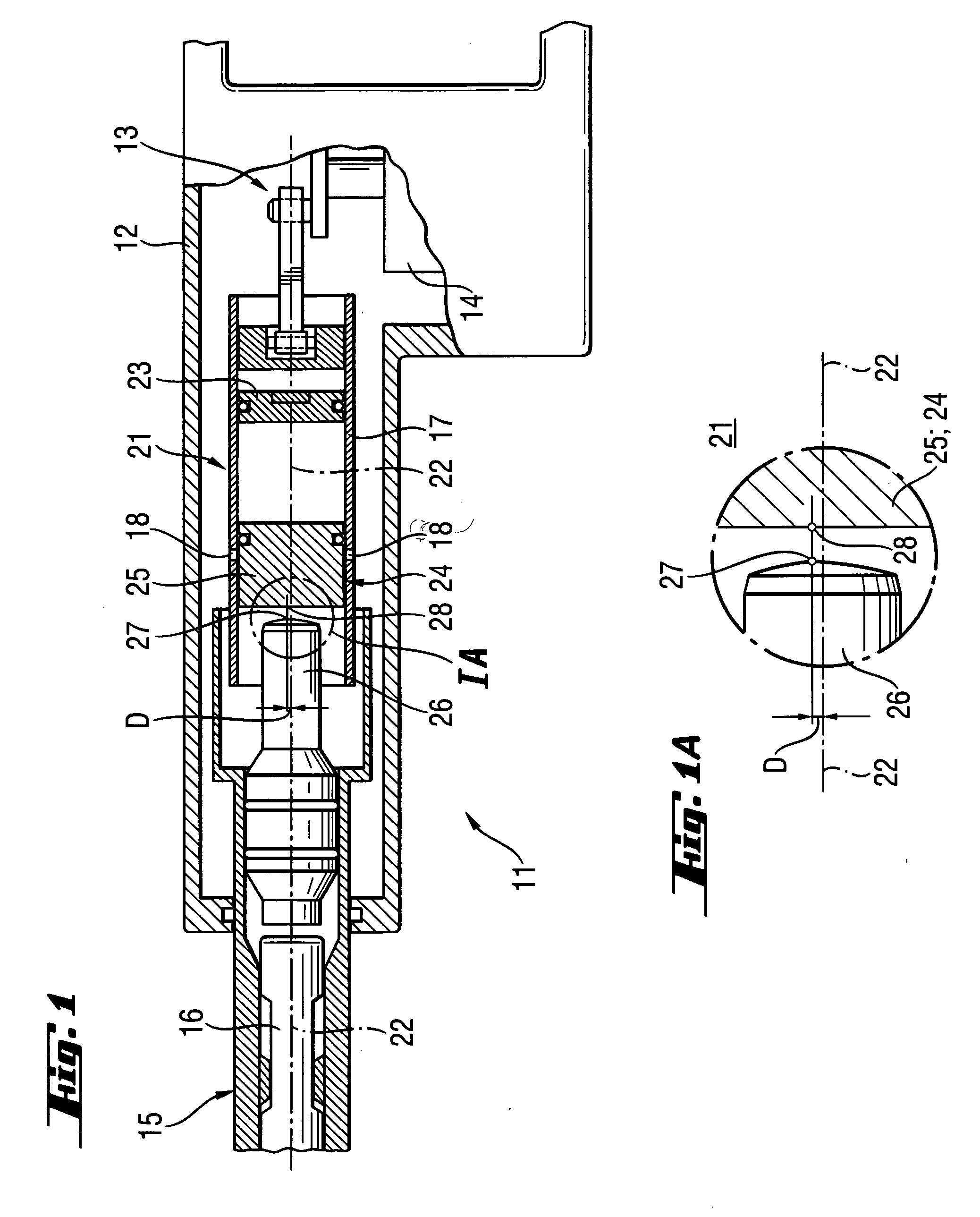
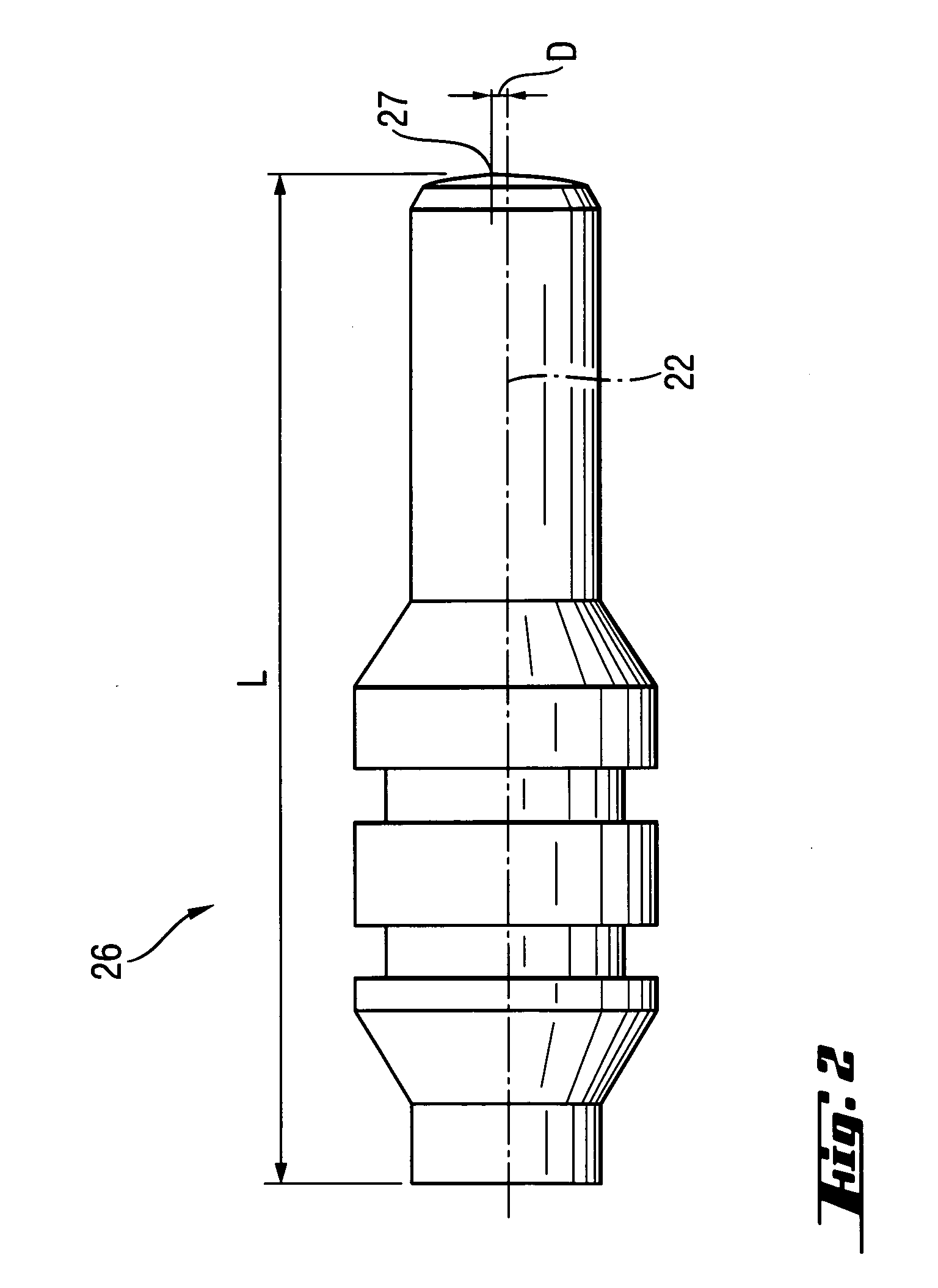
[0029] A chisel hammer 11 according to the present invention, which is shown in FIGS. 1 and 1A, includes a housing 12 in which an electro-pneumatic percussion mechanism 21 and a motor transmission unit 14 are arranged. At the front end of the housing 12, there is provided a tool holder 15 in which a shank 16 of a working tool, not shown, such as, e.g., a spade-shaped chisel is received. The percussion mechanism 21 includes a driving piston 23 reciprocates along a percussion axis 22 in a guide tube 17 by an eccentric device 13 which is driven by the motor-transmission unit 14. Reciprocation movement of the driving piston 23 causes phase-shifted reciprocating movement of a percussion piston 25 that serves as impact element 24. The percussion piston 25 acts on a striker 26 having an exposed contact point 27 located above the percussion axis 22. The percussion piston 25 has a counter-contact point 28 that cooperates with the contact point 27 of the striker. The striker 26 transmits a pu...


PUM

PropertyMeasurementUnit
lengthaaaaaaaaaa
axial lengthaaaaaaaaaa
distanceaaaaaaaaaa

Abstract

A percussion mechanism (21; 41) for a percussion power tool includes an impact element (24; 44) reciprocating along a percussion axis (22; 42) of the percussion mechanism (21; 41) and acting on the striker (26, 46). The contact point (27, 47) and counter-contact point (28, 48) are provided between the striker (26, 46) and the impact element (24, 44), with the contact point (27, 47) being formed as an exposed contact point and being arranged outside of the percussion axis (22; 42).

Description

BACKGROUND OF THE INVENTION [0001] 1. Field of the Invention [0002] The present invention relates to a hammer drill or a chisel hammer with a percussion mechanism including a striker and an impact element reciprocating along a percussion axis of the percussion mechanism and acting on the striker, with the striker and the impact element having cooperating contact point and counter-contact point. [0003] 2. Description of the Prior Art [0004] In hammer drills or chisel hammers with a percussion mechanism, blow or impact pulses are transmitted to a shank of a working tool, which is received in a tool holder of the percussion power tool, by a striker which sometimes is also called an anvil and which is acted upon by an impact element reciprocating along a percussion axis, with the striker and the impact element having cooperating contact point and counter-contact point. [0005] When, e.g., the impact element is formed as a motor-driven driving piston that applies a blow or an impact direc...

Claims


Application Information

Patent Timeline
Patent Type & Authority Applications(United States)
IPC IPC(8): B25D11/00
CPCB25D11/125B25D2250/245B25D2217/0015B25D17/06
Inventor SCHAMBERGER, MICHAELMANSCHITZ, ERWINDAUBNER, CHRISTIANBAUER, JOSEF
Owner HILTI AG
Why Eureka
Try Eureka