Vehicle brake control device

a brake control and vehicle technology, applied in the direction of brake components, braking systems, vehicle components, etc., can solve the problems of difficult inability to accurately detect when the vehicle has stopped moving, and substantial calculation delay, so as to reduce the forward-backward rocking of the vehicle and shorten the braking distance

Inactive Publication Date: 2006-10-26
ADVICS CO LTD
View PDF7 Cites 10 Cited by
  • Summary
  • Abstract
  • Description
  • Claims
  • Application Information

AI Technical Summary

Benefits of technology

[0021] With the above configuration, shortening of the braking distance can be prioritized during emergency braking under ABS control or the like. On

Problems solved by technology

However, when the vehicle speed is low, the vehicle wheels rotate more slowly, and thus a substantial calculation delay occurs.
As a result, it is not possible to accurately detect when the vehicle has stopped moving.
In addition, if control of an anti-lock brake system (ABS) is performed, it is difficult to accurately detect when the vehicle has stopped moving because the vehicle wheels lock just before the vehicle stops moving.
When it is determined that the driver is braking in an emergency, the device does not perform the braking force reduction control for reducing rocking.
However, the device described in JP-A-H11-208439 requires a vehicle body-groun

Method used


Image

  • Vehicle brake control device
  • Vehicle brake control device
  • Vehicle brake control device

Examples


first embodiment

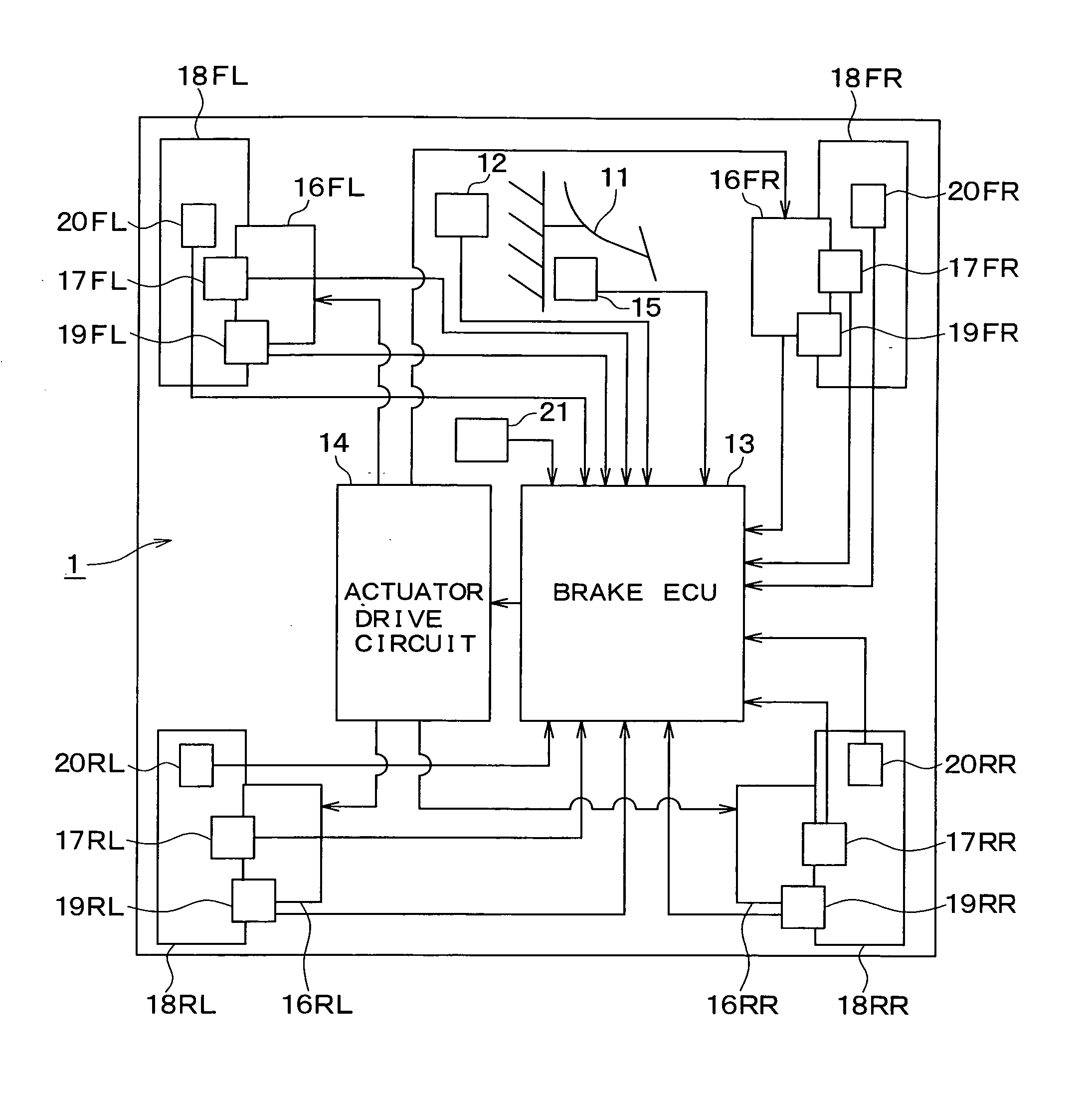
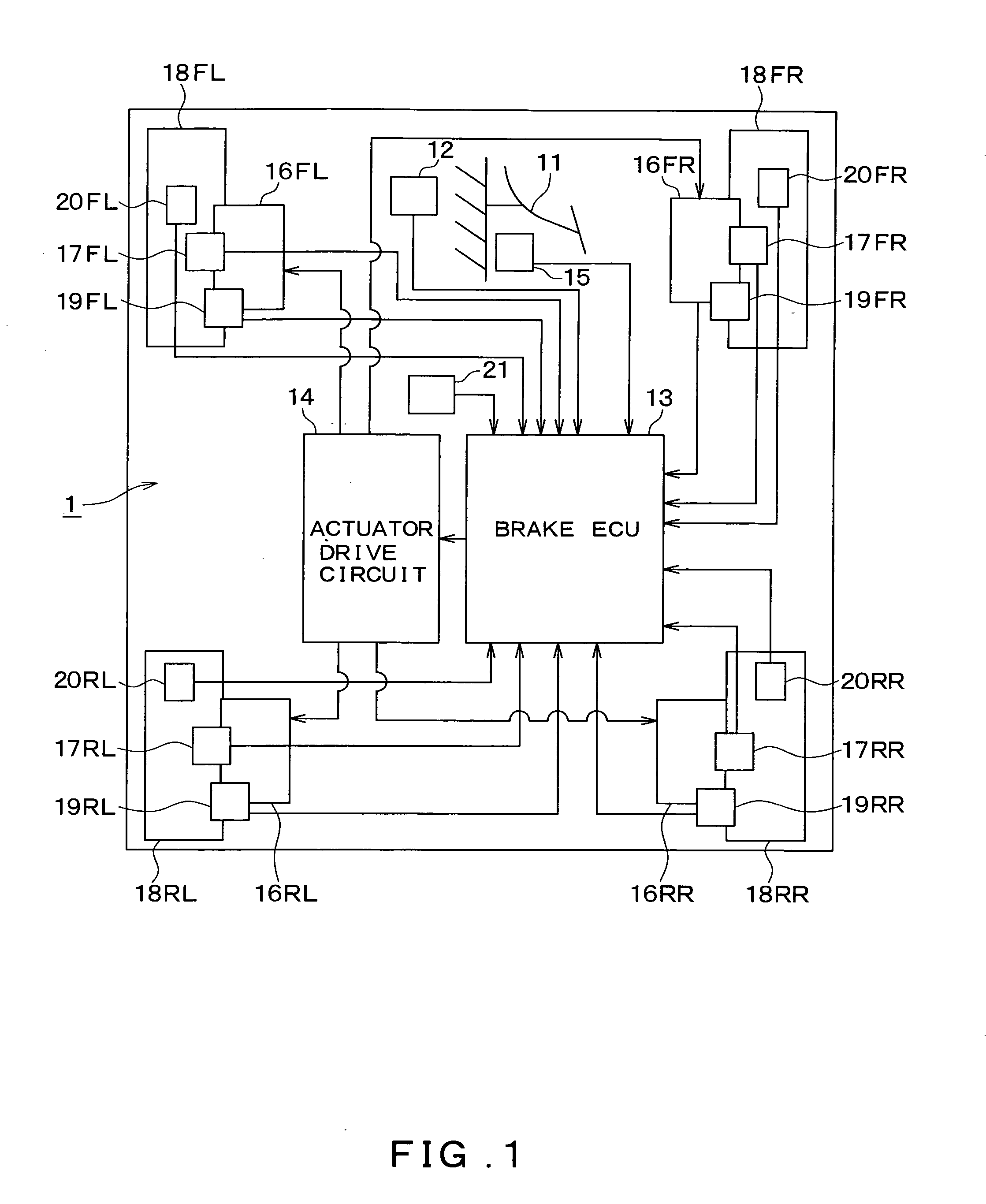
[0034]FIG. 1 shows an overall block diagram of a vehicle brake control device 1 according to a first embodiment. Hereinafter, the configuration of the vehicle brake control device 1 of the present embodiment will be described with reference to FIG. 1.

[0035] Referring to FIG. 1, the vehicle brake control device 1 includes a brake pedal 11; a depression force sensor 12; a brake control unit (hereinafter “brake ECU”) 13; an actuator drive circuit 14; a brake pedal switch 15; actuators 16FL, 16FR, 16RL and 16RR; wheel cylinders 17FL, 17FR, 17RL and 17RR; clamping force sensors 19FL, 19FR, 19RL and 19RR; vehicle wheel speed sensors 20FL, 20FR, 20RL and 20RR; and acceleration sensor 21.

[0036] The brake pedal 11 functions as a brake operation member, and is connected to a stroke simulator (not specifically shown). When the brake pedal 11 is depressed by the driver, a brake fluid pressure that corresponds to the brake pedal depression amount is generated in the stroke simulator.

[0037] Th...

second embodiment

[0064] Next, a second embodiment of the invention will be explained. In this embodiment, the specific details of the braking force reduction control process performed by the brake ECU 13 are different to that of the first embodiment. However, all other structural features of the second embodiment are the same as those of the first embodiment. Accordingly, the explanation given here will not repeat the explanation of these structural features and will instead focus on those features that are different to the first embodiment.

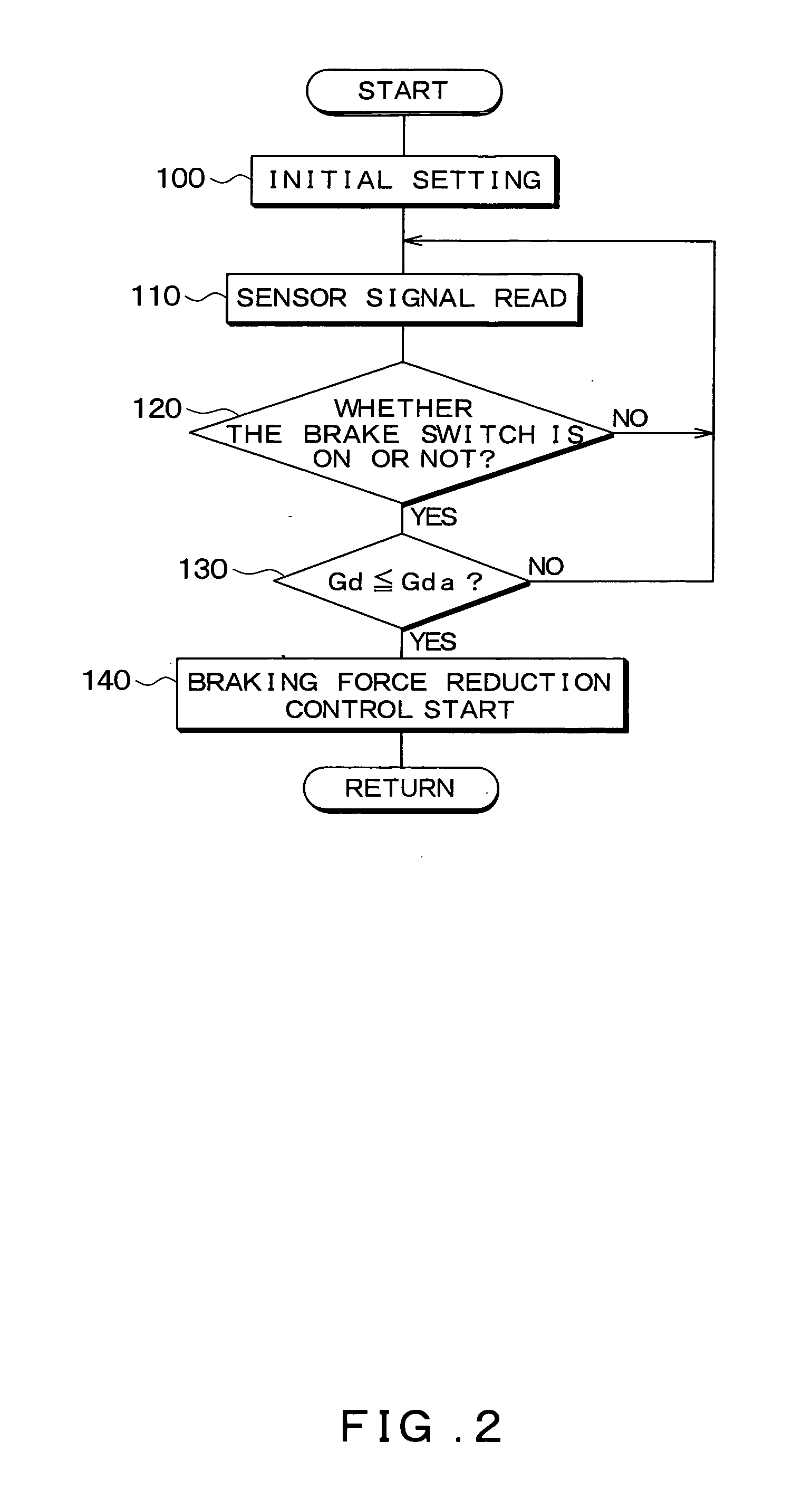
[0065]FIG. 6 is a flow chart of the braking force reduction control process performed by the brake ECU 13 provided in the vehicle brake control device 1 of the second embodiment. The braking force reduction control process is repeatedly performed at a predetermined time interval when, for example, the ignition switch is turned on.

[0066] First, in the processing at 200 to 220, the brake ECU 13 performs the same processing as at 100 to 120 of the first embodiment...

third embodiment

[0076] Next, a third embodiment of the present invention will be described. This embodiment utilizes both (a) a post-stopping braking force control that is performed after the vehicle has stopped like the braking force reduction control process described in the first and second embodiments, and (b) a pre-stopping braking force control that is performed before the time when the vehicle completely stops like the braking force reduction control process described in Japanese Examined Utility Model Application No. H6-8959. Note that, the specific methods used for the post-stopping braking force control and the pre-stopping braking force control are the same as those described in the first and second embodiments and in Japanese Examined Utility Model Application No. H6-8959. Accordingly, the explanation provided here will focus on how switching between the two controls is performed, and a specific description of the controls will be omitted.

[0077]FIG. 8 is a flow chart showing the detail...


PUM


Abstract

A braking force reduction control that reduces the braking force applied to the vehicle wheels is performed when braking of the vehicle is detected. More specifically, the braking force reduction control is started when a speed change of the deceleration of the vehicle has a reducing tendency, namely, when the speed change is equal to or less than a predetermined threshold value.

Description

CROSS REFERENCE TO RELATED APPLICATION [0001] This application is based upon and claims the benefit of Japanese Patent Application No. 2005-123416 filed on Apr. 21, 2005, the content of which are incorporated herein by reference. FIELD OF THE INVENTION [0002] The present invention relates to a vehicle brake control device that can reduce forward and backward rocking of a vehicle that occurs when the vehicle stops, and that can also reduce shock that results from the rocking. BACKGROUND OF THE INVENTION [0003] Japanese Patent Application Publication No. JP-A-H11-208439 and Japanese Examined Utility Model Application No. H6-8959 describe related devices that reduce forward-backward rocking of a vehicle that occurs when the vehicle stops and shock that results from this rocking. [0004] The device described in JP-A-H11-208439 includes (i) means for detecting the braking state of the vehicle, (ii) means for detecting that the vehicle body corresponding to a sprung member has substantiall...

Claims


Application Information

Patent Timeline
IPC IPC(8): B60T8/34
CPCB60T8/172B60T2230/04B60T2201/03
Inventor NITTA, CHIHIROYOKOYAMA, TAKAHISAARAKAWA, HARUOTAKESHITA, TAKAYUKI
Owner ADVICS CO LTD
Why Eureka
Try Eureka